2OM-1064-002.pdf - 第171页
Section 5 Of fset Data 9910-001 5-1 Tg0247-PM-PM

0004-001 4-8 Tg0247-PM-PM

Section 5
Offset Data
9910-001 5-1 Tg0247-PM-PM
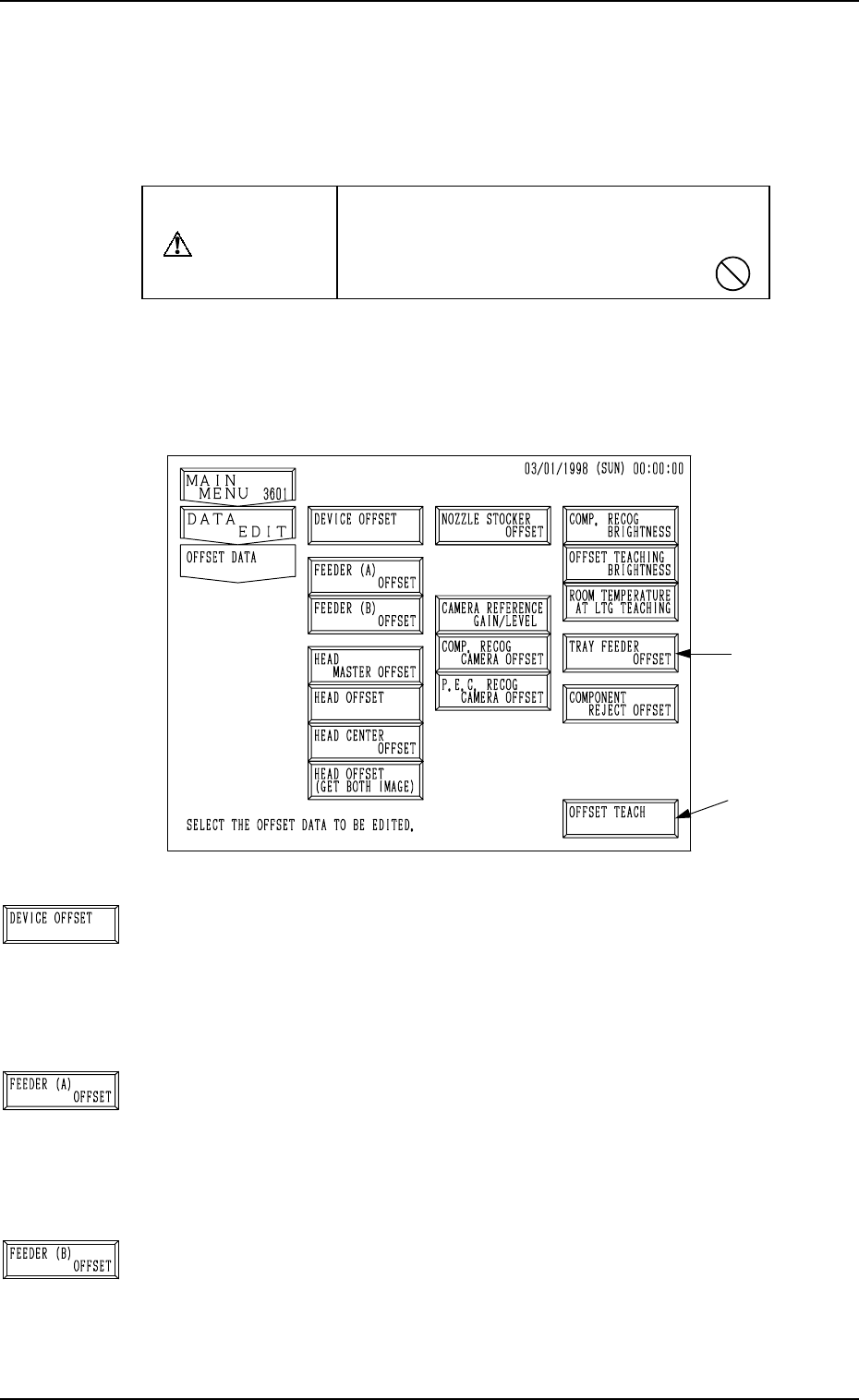
Fig. 5.1
[DEVICE OFFSET] Key
When this key is pressed, the “DEVICE OFFSET” display
appears on the screen, enabling the adjustment of the posi-
tional and angular deviations based on the design dimensions
representing the A/B beam driving X/Y coordinates viewed
from the P.C.B. positioning X/Y coordinates.
[FEEDER (A) OFFSET] Key
When this key is pressed, the “FEEDER (A) OFFSET” dis-
play appears on the screen, enabling the adjustment of the po-
sitional deviation based on the design dimensions represent-
ing the component pick-up position and height of the feeder
for each individual feeder slot Nos. (FDR. NO.).
[FEEDER (B) OFFSET] Key
When this key is pressed, the “FEEDER (B) OFFSET” dis-
play appears on the screen, enabling the correction of the varia-
tions, etc., for each individual feeders.
1. OFFSET DATA Display
This session describes how to set various kinds of offset data for each device
position adjustment related to machine operation, for the camera system re-
lated to placement accuracy, for the heads, and for the nozzles.
CAUTION
Do not change the parameters unless neces-
sary. They are factory-adjusted and set upon
shipment of the machine.
• Some parameters are automatically computed through teaching operation.
When the [OFFSET DATA] key is pressed at the “DATA EDIT” display, the
following display appears on the screen.
Note: The -marked function is optional.
1. OFFSET DATA Display
*1
9910-001 5-2 Tg0247-PM-PM