2OM-1064-002.pdf - 第162页
• The first component pick-up position is assumed to be “X: 3, Y : 2”. z : Component Picked Normally { : Component Left Behind Shadowed : Mispick 4. TRA Y MA TRIX MODE Display (Option) z z z z z z { { {{ z zz zz z z z z …
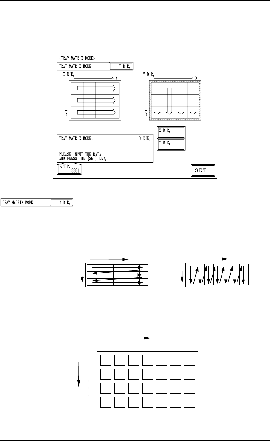
Fig. 3.8
TRAY MATRIX MODE
Set “X DIR.” or “Y DIR.” (direction in which components
should be taken out) in this data box.
In normal cases, “Y DIR.” should be selected.
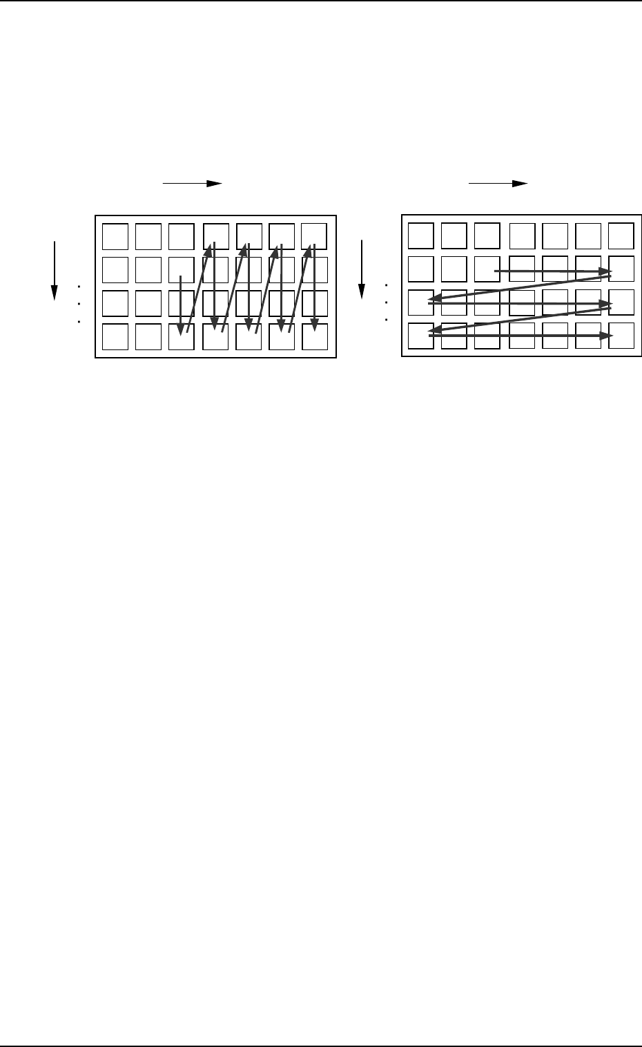
Fig. 3.9 shows the order (arrow directions) in which compo-
nents are taken out.
4. TRAY MATRIX MODE Display (Option)
When the [TRAY MATRIX MODE] key is pressed at the “DEVICE DATA”
display, the following display appears on the screen.
4. TRAY MATRIX MODE Display (Option)
9910-001 3-13 Tg0247-PM-PM
{
: Component Existing
×
: No Component (Taken Out)
{{{
{{{{{
{{{{{
×
×××
×
×
×××
{{
{{
{{
Y
1
2
99
1
X
99
・
・・
・
・
・・
・
・
・・
・
・
・・
・
・
・・
・
・
・・
・
3
2
X
Selection of “X DIR.”
Y
X
Selection of “Y DIR.”
Y
Fig. 3.10
Fig. 3.9
Example: The tray is in the condition (in the middle of pro-
cess) shown in Fig. 3.10.
• The first component pick-up position is assumed to be “X:
3, Y: 2”.
z : Component Picked Normally
{ : Component Left Behind
Shadowed : Mispick
4. TRAY MATRIX MODE Display (Option)
z
z
z
zz
z{{
{{
z
zz
zz
zz
z
z
z
z z
z
z
z
z
z
z
z z z
z
z z
zz
z
z
Selection of “Y DIR.”
Selection of “X DIR.”
Y
1
2
99
1
X
99
・
・・
・
・
・・
・
・
・・
・
・
・・
・
・
・・
・
・
・・
・
3
2
1
X
99
・
・・
・
・
・・
・
・
・・
・
・
・・
・
・
・・
・
・
・・
・
3
2
Y
1
2
99
××
×××
××××
××
××× × ×××
Fig. 3.11-1 Fig. 3.11-2
9910-001 3-14 Tg0247-PM-PM

Section 4
Automatic Operation Set-Up
9910-001 4-1 Tg0247-PM-PM