2OM-1064-002.pdf - 第176页
Fourth Page Fig. 5.3-4 *1 2. DEVICE OFFSET Display 9910-001 5-6 Tg0247-PM-PM
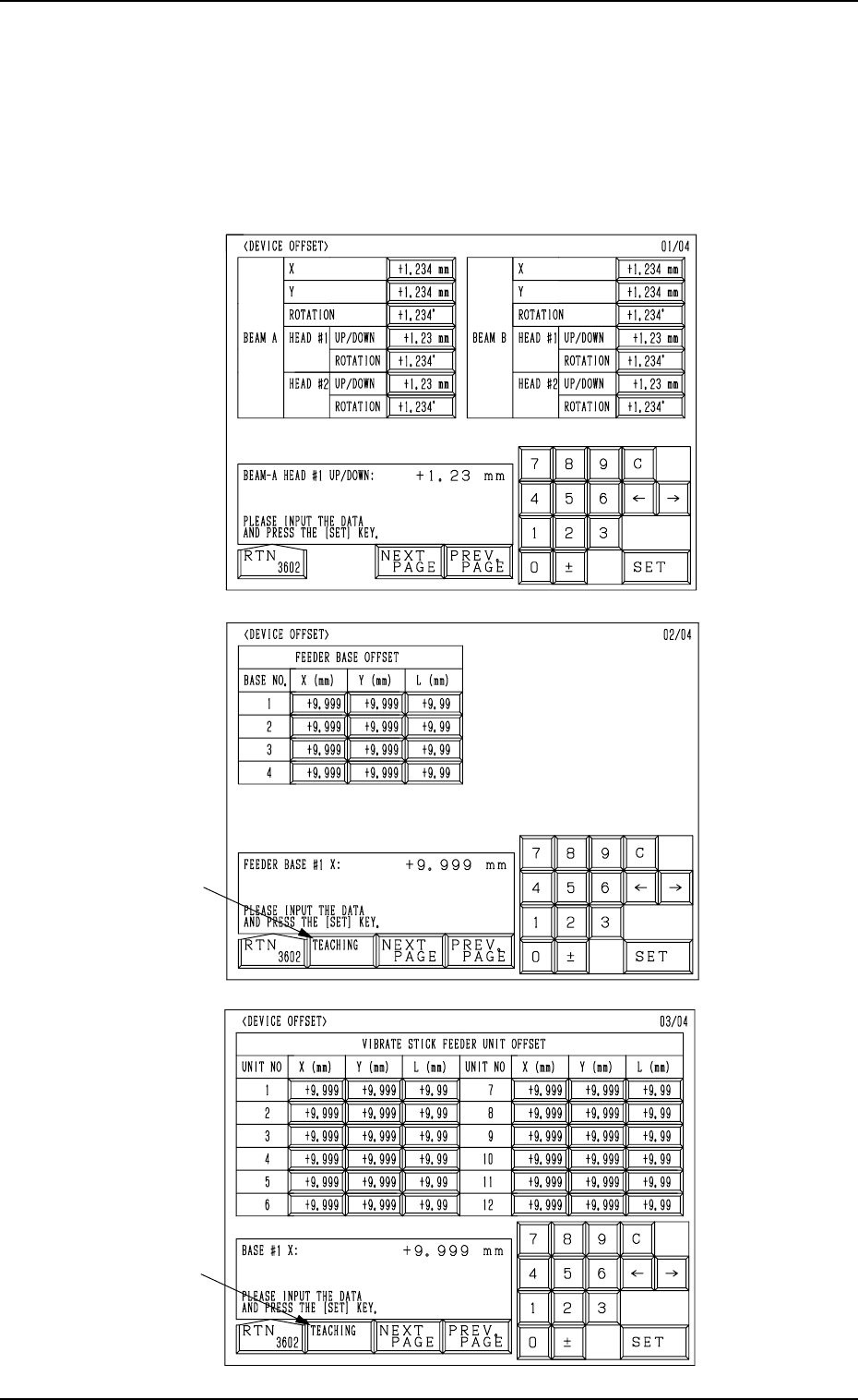
Fig. 5.3-3
First Page
Second Page
Third Page
Fig. 5.3-2
Fig. 5.3-1
*1
*1
2. DEVICE OFFSET Display
9910-001 5-5 Tg0247-PM-PM
2. DEVICE OFFSET Display
When the [DEVICE OFFSET] key is pressed at the “OFFSET DATA” display,
the following display appears on the screen.
Every time the [NEXT PAGE] or the [PREV. PAGE] key is pressed, another or
previous page appears on the screen.
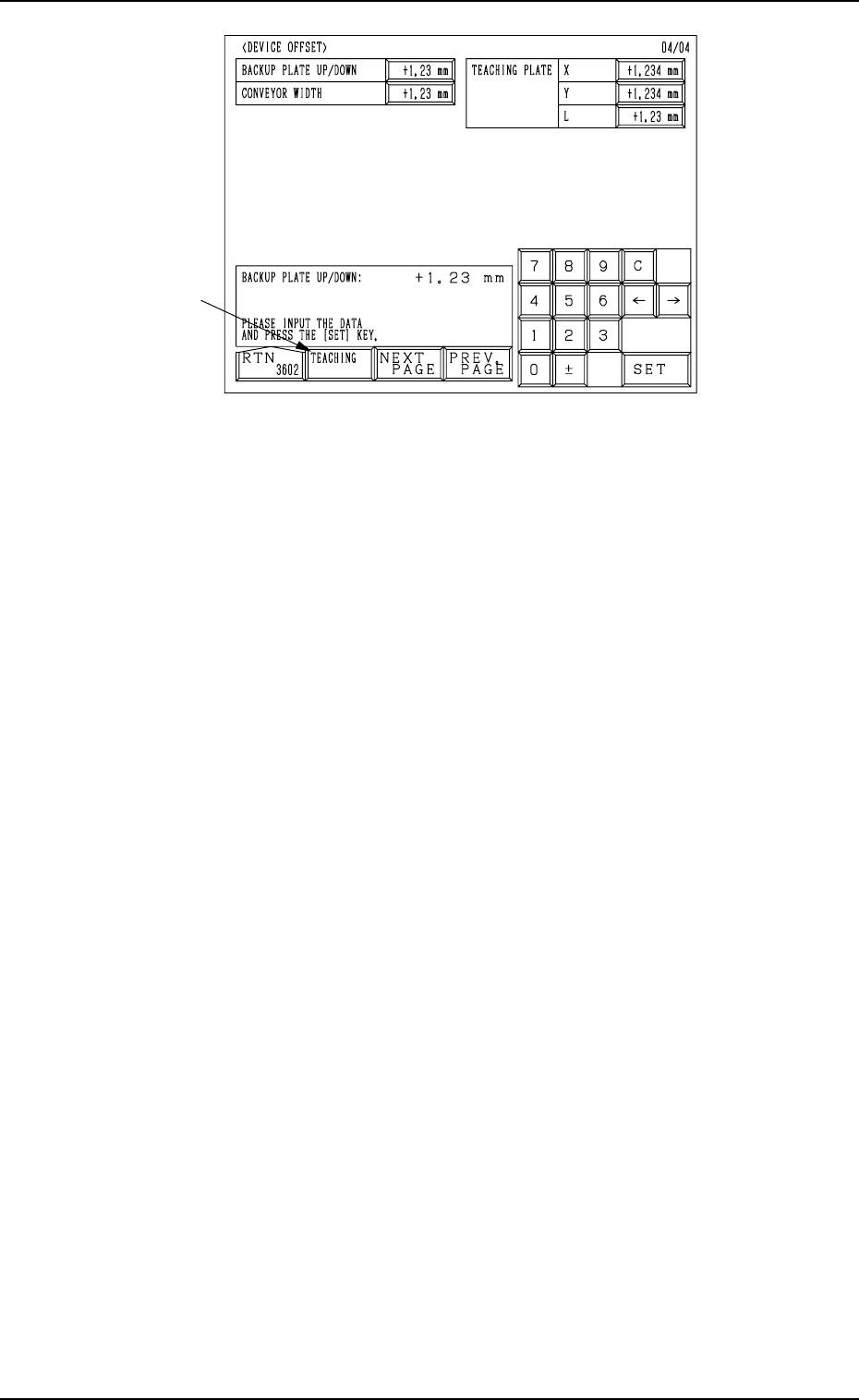
Fourth Page
Fig. 5.3-4
*1
2. DEVICE OFFSET Display
9910-001 5-6 Tg0247-PM-PM
First Page
BEAM A X (Horizontal), Y (Vertical), and ROTATION
The set offset data is used to adjust the positional and angular
deviations based on the design dimensions representing the
beam A driving X/Y coordinates (BeamA-X/Y: Origin A0)
viewed from the P.C.B. positioning X/Y coordinates (PL-XY:
Origin P0). The values based on the PL-X and PL-Y coordi-
nates must be entered in the data boxes.
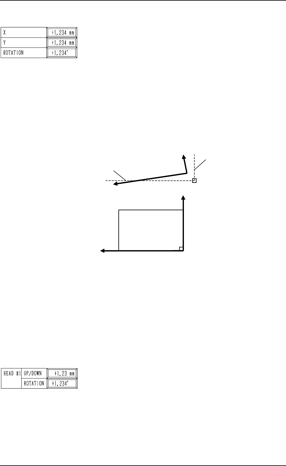
• Design Values
X: -94.000 mm, Y: +496.000 mm
Origin A0 is the scanning coordinate center of the P.E.C.
camera installed on Beam A when Beam-A X/Y axis are
located at their origins.
This offset data is automatically calculated through teach-
ing operation which is performed, using a jig P.C.B.
Fig. 5.4
When the beam A driving X/Y coordinates (actual values) are
those as shown above, the offset parameters representing the
X (horizontal) and Y (vertical) values must be provided with
minus (-) signs and the offset parameter representing the rota-
tion (angle) with a plus (+) sign.
BEAM A/BEAM B HEAD #1/HEAD #2, UP/DOWN
This offset data (offset data for the origin positions of the head
up/down axis) is used to adjust the distance between the P.C.B.
positioning reference point on the upper surface of a P.C.B.
and the origins of the head up/down axis.
Plus parameters entered in these data boxes increase the down-
ward movement of the head.
9910-001 5-7 Tg0247-PM-PM
2. DEVICE OFFSET Display
P0
Beam A Origin Position (Design Value): A0
P.C.B. Positioning X/Y
Coordinates
PL-XY
PL-X (+)
PL-Y (+)
BeamA-X(+) [Design Value]
BeamA-Y(+) [Design Value]
BeamA-X(+) [Actual Value]
BeamA-Y(+) [Actual Value]
(Front Side of Machine)
Top View (based on the reference point “R-FRONT”)