2OM-1064-002.pdf - 第25页
2.3.1 Operation Data (Standard) [PROGRAM CHECK] Key When this key is pressed, the edited pattern program is checked. First Page P .C.B. SIZE X (Horizontal), Y (V ertical) Enter parameters (outmost dimensions) in the “X” …
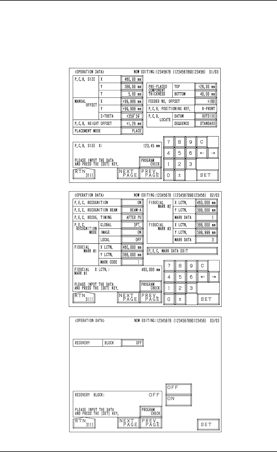
Fig. 2.6-1
Fig. 2.6-2
Fig. 2.6-3
First Page
Second Page
Third Page
2.3 OPERATION DATA Display
When the [OPERATION DATA] key is pressed at the “PATTERN PROGRAM
EDIT” display, the following display appears on the screen.
Every time the [NEXT PAGE] or the [PREV. PAGE] key is pressed, another or
previous page appears on the screen.
2. Pattern Program
9910-001 2-12 Tg0247-PM-PM
2.3.1 Operation Data (Standard)
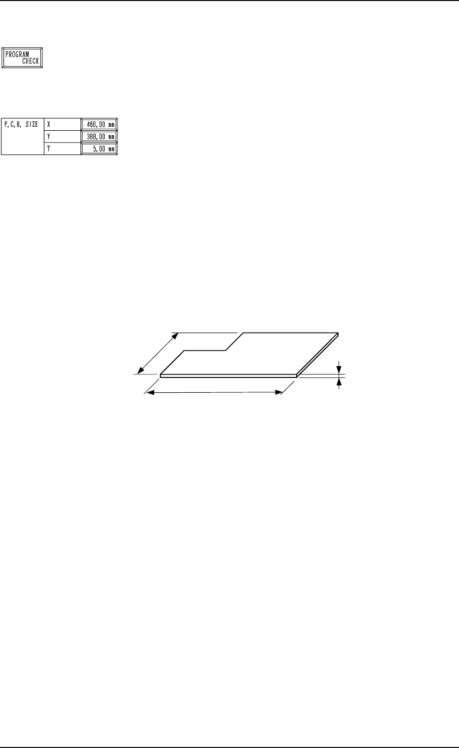
[PROGRAM CHECK] Key
When this key is pressed, the edited pattern program is checked.
First Page
P.C.B. SIZE
X (Horizontal), Y (Vertical)
Enter parameters (outmost dimensions) in the “X” and “Y”
data boxes. (Unit: mm)
Note: Be sure to set correct parameter in the “X” data box
because the set parameter is used to automatically cor-
rect the placement position when a parameter is se-
lected for the label “P.C.B. LOCATE MODE” at the
“P.C.B. TRANSFER MODE SET-UP” display.
The set parameter in the “Y” data box must be used as
a target width for the conveyor width automatic ad-
justment operation.
When a P.C.B. has a cutout, the dimensions shown
below represent each parameter.
Fig. 2.7
•
Data Input Range
X : 50.00 to 460.00 mm
Y : 50.00 to 381.00 mm
T (Thickness)
Set a parameter (thickness of P.C.B.) in the data box.
The set parameter must be used as a target value for the backup
table ascending position when a P.C.B. is clamped by the clamp
plates and positioned.
• Data Input Range: 0.30 to 5.00 mm
9910-001 2-13 Tg0247-PM-PM
2. Pattern Program
P.C.B.
X
(
Horizontal
)
Y (Vertical)
T (Thickness)
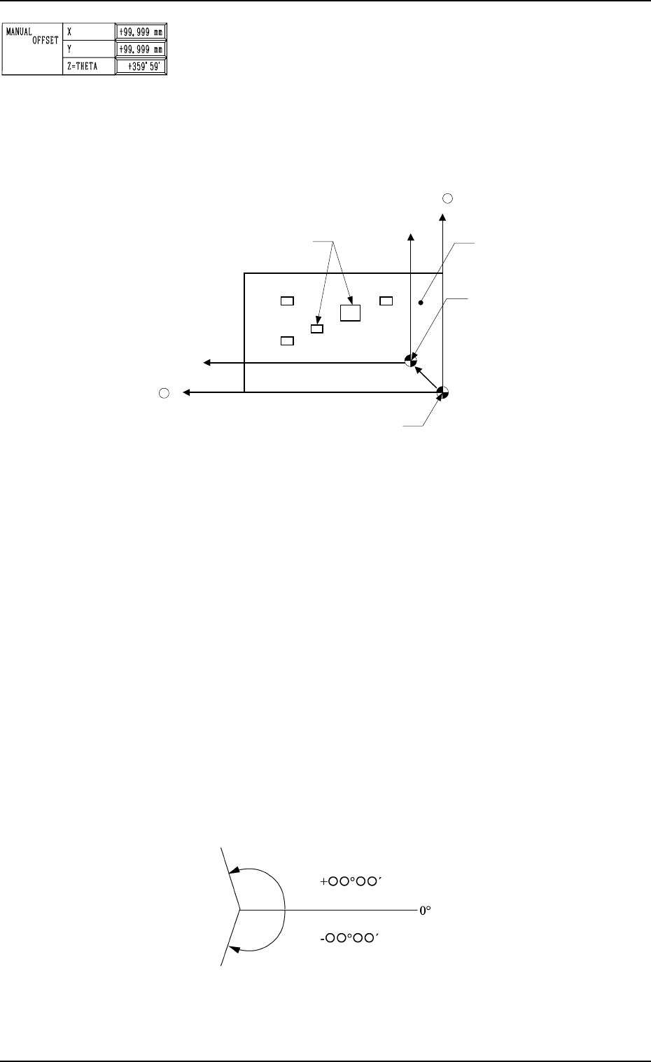
MANUAL OFFSET
X (Horizontal), Y (Vertical)
Set parameters (offset data) in the data boxes. The set param-
eters are used as offset data to correct the difference (x, y)
between the reference point (X and Y in the placement data
used to indicate the placement position) in the coordinate sys-
tem and the reference point for machine positioning based on
P.C.B. positioning to be set up when a P.C.B. is positioned.
2. Pattern Program
Fig. 2.8
The set parameters represent the values indicating the refer-
ence point in the coordinate system (placement data) based on
the reference point for machine positioning to be set up when
a P.C.B. is positioned. When a P.C.B. shown above is used,
parameters must be entered with a plus (+) sign for both X and
Y.
•
Data Input Range
X : -99.99 to +99.99 mm
Y : -99.99 to +99.99 mm
Z=THETA
Set a parameter (offset value for the angle of the component to
be placed) in the data box.
The set parameter is added commonly to the placement angle
data (Z data in the placement P data) for each individual com-
ponent to be placed.
To correct the angle of component placement counterclock-
wise, a parameter must be entered with a plus (+) sign. A mi-
Components
Y +
Coordinate Reference
for Placement Data
Reference Point for Machine Positioning: “Outline” Reference
P.C.B.
X +
nus (-) sign must be affixed for clockwise correction.
Plane View
Fig. 2.9
• Data Input Range: -359°59´ to +359°59´
0004-002 2-14 Tg0247-PM-PM