YSM20R_YSM20WR_Ope_E.pdf - 第111页
2-8 2 Basic operation 2. Operation screen and buttons The basic configuration and operation methods of the operation screens are explained in this section. n NOTE Because standard specification systems have no keyboard or…
2-7
2
Basic operation
n
Others
Code Error name and description
Ea00109
EMERGENCY STOP FUNCTION DURING MOUNT
State
EMERGENCY STOP FUNCTION is executed during mounting sequence. So, there is danger that mount
sequence finished under the unusual condition. (Can it stop automatically after it installs it when an automatic
driving is restarted, and the image at the installation position be confirmed.)
Cause Emergency stop was triggered during component placement.
Action Use "trace" to check whether the component is placed at the specified point.
Ea00818
QUICK STOP ACTIVE
State QUICK STOP FUNCTION is now active.
Cause Emergency stop was triggered by the "conveyor width safety check sensor".
Action Check the status of the conveyor width safety check sensor.
Ea02722
DON'T YOU NEED HALFWAY CONTINUE?
State
A board that is not finished to mount exist on the mounting position. If you continue auto running, a halfway
board may be transferred. Please confirm the board condition and execute halfway continue command if
necessary.
Cause
A board for which component mounting is not completed is left in the component placement position. If
automatic operation continues as is, then the unfinished board may be transferred downstream.
Action
Check the board in the component placement position. When it is not finished, run "Halfway Continue"
command to resume component mounting on that board.
Ea02889
EMERGENCY STOP FUNCTION DURING PICK
State
EMERGENCY STOP FUNCTION is executed during picking sequence. There is a chance that the picking
sequence finished under suspicious conditions. Please check condition of the component.
Cause
Emergency stop was triggered during component pickup. Component pickup operation might have been
unstable.
Action Check how the component is being picked up.
Ea07871
CAN NOT EXECUTE COMMAND
State
Can not execute this command , because RESET is not finished completely. Please try the RESET command
again, and finish it.
Cause Unable to run commands since reset is not complete.
Action Perform a reset again.
Ea01277
X1 Axis 2nd LIMIT OVER
State Move the axis until error message disappears. The "EMERGENCY STOP" light will go off.
Cause X1-axis secondary limit was exceeded.
Action Move the X1 axis by hand to a safe position.
Ea01278
Y1 Axis 2nd LIMIT OVER
State Move the axis until error message disappears. The "EMERGENCY STOP" light will go off.
Cause Y1-axis secondary limit was exceeded.
Action Move the Y1 axis by hand to a safe position.
2-8
2
Basic operation
2. Operation screen and buttons
The basic configuration and operation methods of the operation screens are explained in this section.
n
NOTE
Because standard specification systems have no keyboard or mouse, all operations are performed from the touch-
panel. A dialog box displays at parameter input operations, and the desired operations and inputs can then be
performed with the touch-pen.
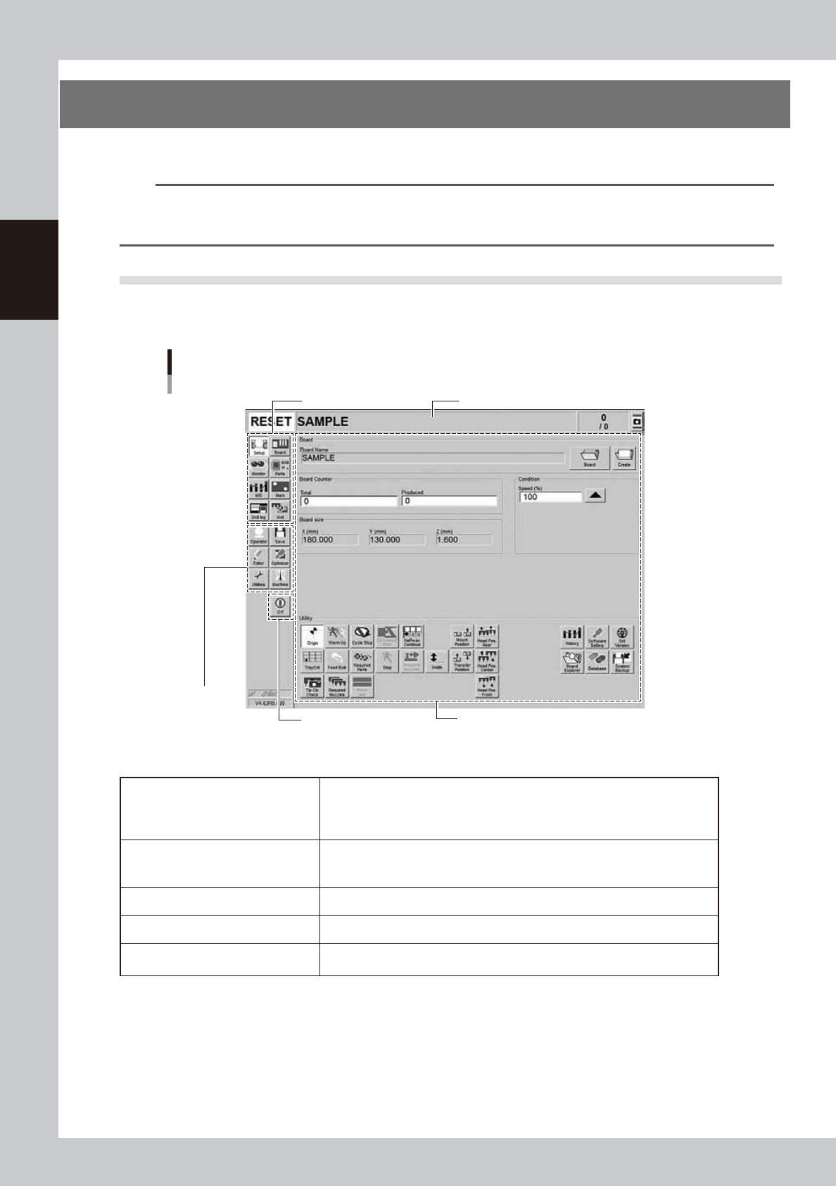
2.1 Basic configuration of operation screen
The operation screen consists of "Status area", "Main menu button area" and "Submenu button and parameter
area" as shown below.
Main menu button area 1
Main menu
button area 2
Main menu button area 3
Status area
Operation screen basic configuration
Setup screen ( Example of Dual-stage)
Submenu button and parameter area
24200-KMK-00
n
Area on screen
Status area
Displays the current machine status on the left end, the selected board name in
the middle, and the number of boards that have been produced on the right end.
(When producing with both lanes of dual-lane, the Board Name and Board
Counter of each lane are displayed in 2 rows.)
Main menu button area 1
Shows the main menu buttons used to operate the machine. The submenu
button and parameter area will change according to the selected main menu
button.
Main menu button area 2 Shows the menu buttons used to call up auxiliary functions of the machine.
Main menu button area 3 Shows the [Off] button to turn off the machine.
Submenu button and parameter area
Displays the submenu buttons and parameters for machine operation and data
setting. This area will change according to the selected main menu button.
2-9
2
Basic operation
n
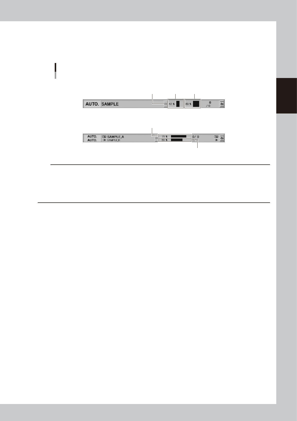
"Mount compilation rate" on status area
The "Mount compilation rate" is displayed on the status area if the software version is 4.65 R1.000 or later.
The mount status on board per stage/lane can be checked.
Note that [>>] / [<<] button on the status area hides/reveals the mount compilation rate.
Status area
Display of "Mount compilation rate"
Stage 1
Reveal/Hide
button
Stage 2
Lane 1
Lane 2
Dual-stage type
Dual-lane type
24236-KMK-00
TIP
The mount compilation rate is calculated with the following formula.
Mount compilation rate (%) = (The number mount is completed / The number of all mounts) × 100
Note that the mount point where the mounting is not performed due to the bad mark for instance is not included in
the mount completion rate. Therefore, the final mount compilation rate may not be 100%.
Additionally, the skipped mount point is not included in the calculation. If no mount data exists, "-" is displayed.
The mount compilation rate returns to 0% by reloading a board data.