YSM20R_YSM20WR_Ope_E.pdf - 第59页
1-26 1 Unit names and functions n Head No. and feeder set No. T he feeder set number which can be used by eac h head depends on the head assembly configuration, X-axis mov able range and the table location. T he tables b…
1-25
1
Unit names and functions
4. Component supply section
4.1 Machine layout
A feeder plate to install the tape feeder, etc., and a power connector or an air connector to drive the option
devices are installed in the feeder setting section.
n
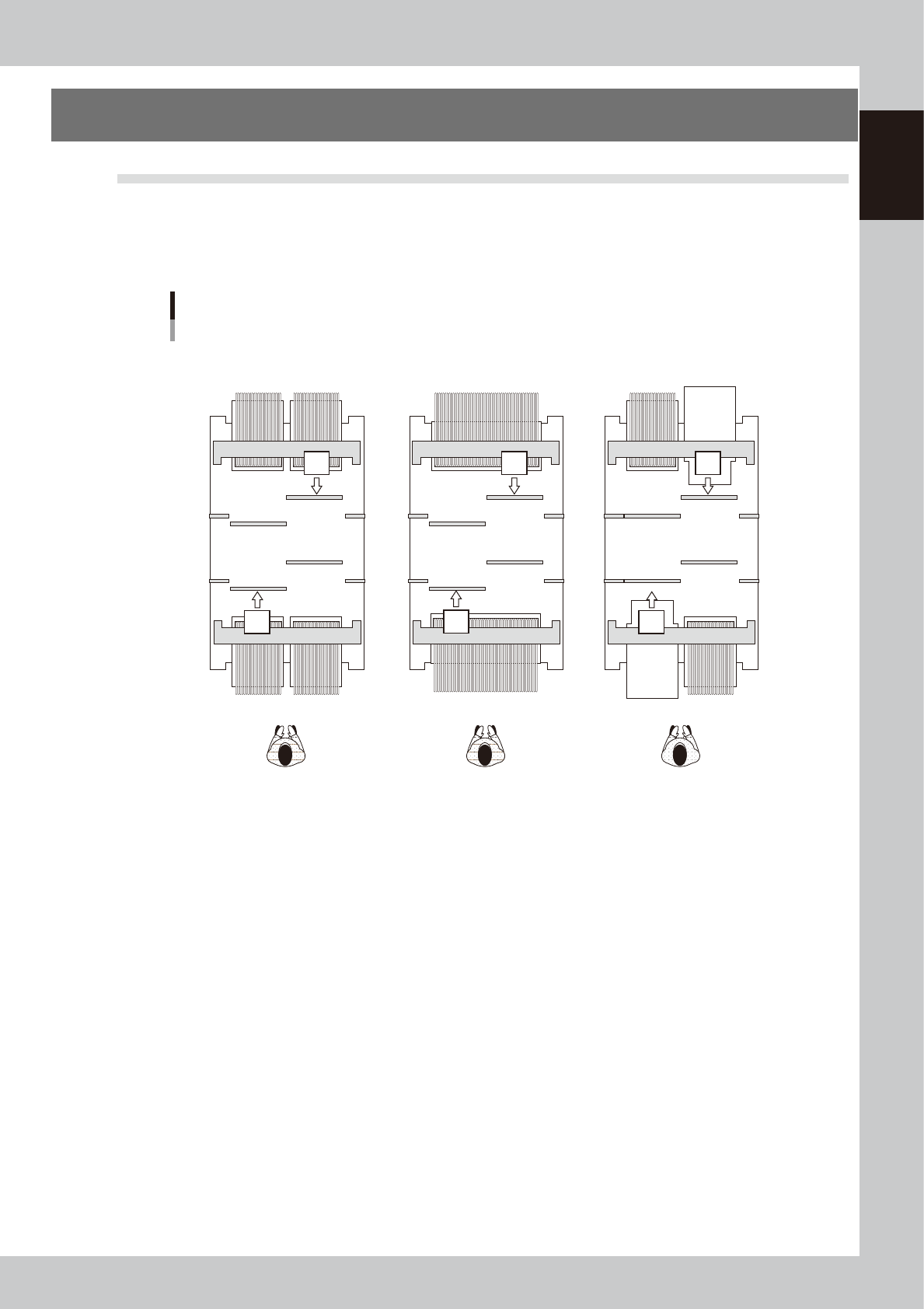
Component supply formats
1 32 33 6464
164 132 101 164 133
1 70
170 101
cATS10 or
sATS30 or
sATS30NS
cATS10 or
sATS30 or
sATS30NS
Machine layout
Example of dual-stage, 2-beam
32-reel feeder exchange carriage x 4 units 70-reel fixed bank x 2 Front or rear ATS
23116-KMK-00
1-26
1
Unit names and functions
n
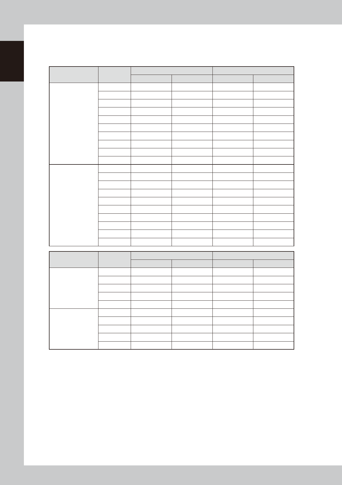
Head No. and feeder set No.
The feeder set number which can be used by each head depends on the head assembly configuration, X-axis movable
range and the table location.
The tables below show feeder set numbers that can be accessed by each head of the machine.
HM Head Head No.
Feeder exchange carriage (32-reel) Fixed (70-reel)
Front/A table Rear/B table Front/A table Rear/B table
1-beam
1 6 – 64 101 – 155 6 – 70 101 – 161
2 5 – 63 101 – 156 5 – 69 101 – 162
3 4 – 62 101 – 157 4 – 68 101 – 163
4 3 – 61 101 – 158 3 – 67 101 – 164
5 2 – 60 101 – 159 2 – 66 101 – 165
6 1 – 59 102 – 160 1 – 65 102 – 166
7 1 – 58 103 – 161 1 – 64 103 – 167
8 1 – 57 104 – 162 1 – 63 104 – 168
9 1 – 56 105 – 163 1 – 62 105 – 169
10 1 – 55 106 – 164 1 – 61 106 – 170
2-beam
1 1 – 55 101 – 155 1 – 61 101 – 161
2 1 – 56 101 – 156 1 – 62 101 – 162
3 1 – 57 101 – 157 1 – 63 101 – 163
4 1 – 58 101 – 158 1 – 64 101 – 164
5 1 – 59 101 – 159 1 – 65 101 – 165
6 2 – 60 102 – 160 2 – 66 102 – 166
7 3 – 61 103 – 161 3 – 67 103 – 167
8 4 – 62 104 – 162 4 – 68 104 – 168
9 5 – 63 105 – 163 5 – 69 105 – 169
10 6 – 64 106 – 164 6 – 70 106 – 170
FM Head Head No.
Feeder exchange carriage (32-reel) Fixed (70-reel)
Front/A table Rear/B table Front/A table Rear/B table
1-beam
1 6 – 63 101 – 155 6 – 63 101 – 161
2 4 – 61 101 – 157 4 – 61 101 – 163
3 2 – 59 102 – 159 2 – 59 102 – 165
4 1 – 57 104 – 161 1 – 57 104 – 167
5 1 – 55 106 – 163 1 – 55 106 – 169
2-beam
1 1 – 55 101 – 155 1 – 61 101 – 161
2 1 – 57 101 – 157 1 – 63 101 – 163
3 2 – 59 102 – 159 2 – 65 102 – 165
4 4 – 61 104 – 161 4 – 67 104 – 167
5 6 – 63 106 – 163 6 – 69 106 – 169
1-27
1
Unit names and functions
4.2 Supply from fixed feeder bank
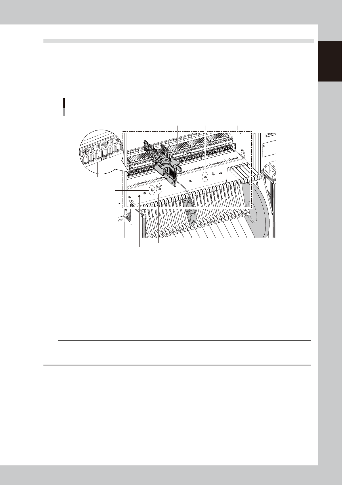
4.2.1 70-reel fixed feeder bank
A tape feeder or a stick feeder is set up on the feeder plate on the feeder bank. The feeder plate has a connector
for the feeder used for connections to supply the set feeder with electrical power and bridges signal exchange
with the machine. The inside of the feeder bank has a tape cutter to cut off empty tape and dispose of after
supplying components.
Component supply unit
70-reel fixed feeder bank
Feeder connectors
Power connectorFeeder plate
Tape cutter installed inside (option)
Feeder bank
Air connector
Harness connector for the QFP recovery conveyor.
23117-KMK-00
Power connector
A power connector for option devices, such as stick feeder.
Air connector
An air connector for option devices, such as air blow tool. Connect an air tube with an outside diameter of
φ
4 to this
connector to supply the air from this machine to the option devices.
Harness connector
The connector of the harness for signals to use the QFP recovery conveyor.
The QFP recovery conveyor uses a power connector, too.
n
NOTE
here are three types of tape feeders: SS feeder, ZS feeder and Auto loading feeder. This machine is applicable with
any types. However the machine whose type is 70-reel fixed feeder bank needs to have the safety cover opened
when feeders are replaced.