YSM20R_YSM20WR_Ope_E.pdf - 第98页
1-65 1 Unit names and functions 8.2 Ionizer T he ionizers are installed to defuse the static electricity . Note that the performance and capability of the ionizer to remove static electricity depends on the oper ating en…
1-64
1
Unit names and functions
8. Other options
There are a coplanarity checker, an ionizer and an UPS (Uninterruptible Power Supply) as options else for
this machine.
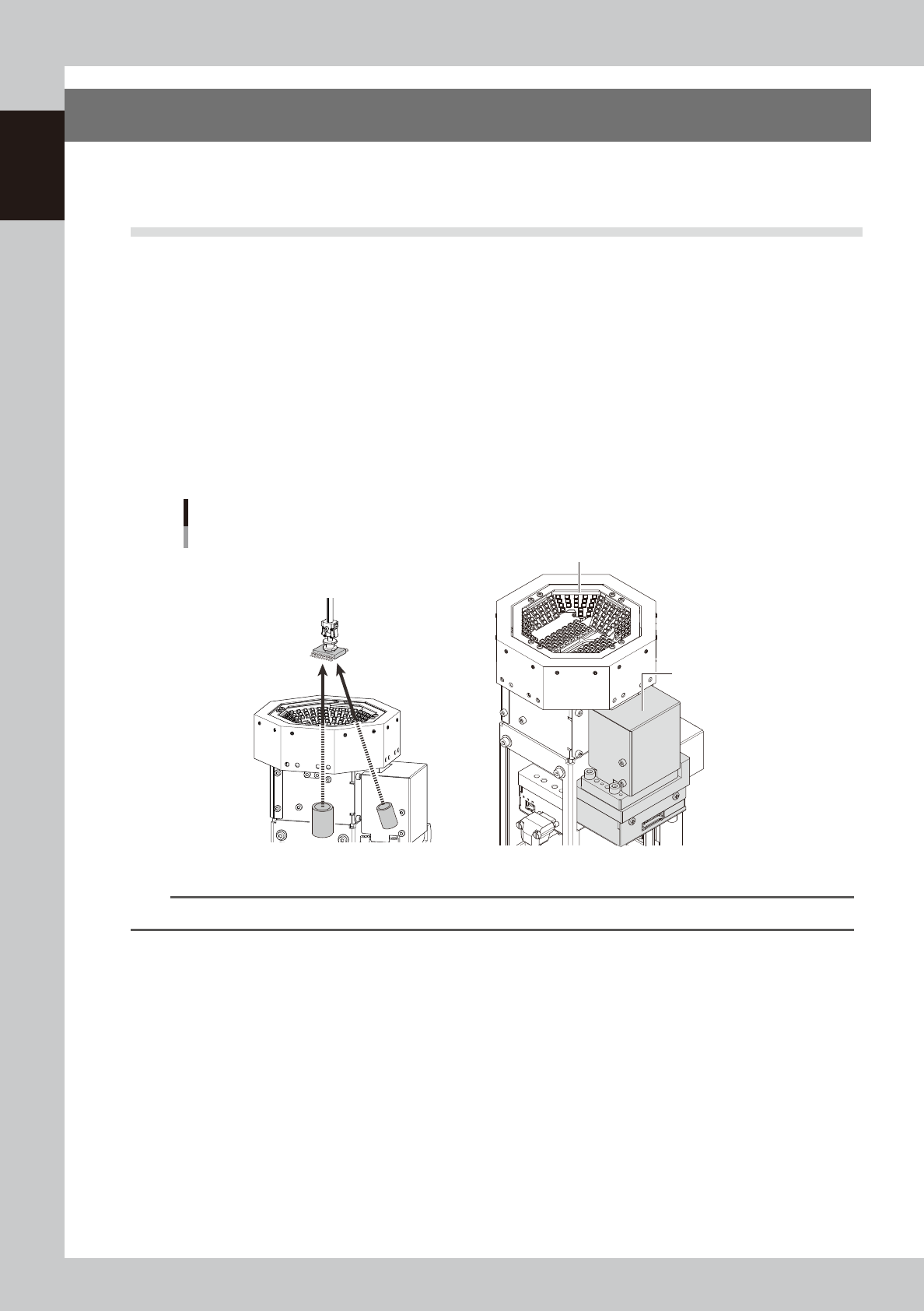
8.1 Coplanarity checker
The multi-view camera with a coplanarity checker can be selected as an option.
In addition to the multi camera recognizing components, by using the coplanarity checker to recognize
components diagonally, it measures lead linearity and coplanarity of QFP/SOP leads or BGA bumps at high
speeds, then determines "pass/fail"
The coplanarity checker has the following two functions:
• Coplanarity check
Inspects uniformity of the lead bottom against the seating plane of components having wire leads or solder balls so that
the fault mounting due to such as leads floating are prevented.
• Component recognition height check
Prevents lead components from being mounted in an inverted position.
Coplanarity checker
Multi-view camera
Coplanarity checker
23132-KMK-00
n
NOTE
For instructions on how to use the coplanarity checker, refer to the programming manual.
1-65
1
Unit names and functions
8.2 Ionizer
The ionizers are installed to defuse the static electricity.
Note that the performance and capability of the ionizer to remove static electricity depends on the operating
environment or the materials and shape of the items that the static electricity is removed.
Such performance or capability is not guaranteed.
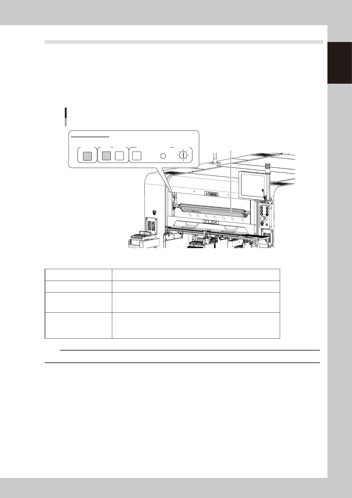
The ionizer of this machine is installed behind the machine safety cover. The ionizer when shipped from the
factory faces around the component pick up position of the feeder. The installation angle can be changed
according to the specifications of the board and the components.
Ionizer
Ionizer
POWER
ALARMRUN
CLEANING
RESET
CLEANING TIMER
T SELECT
Ionizer indicator panel
23133-KMK-00
n
Ionizer indication
POWER The green LED lights up when the electric power is supplied normally.
RUN The green LED stays on during the normal operation.
ALARM
The red LED lights up if the discharge needle has deteriorated or an inner unit/
device is experiencing an error. The machine main body also generates an
alarm.
CLEANING TIMER
When the duration of time set up by operating the trimmer of T.SELECT has
expired, the “CLEANING” yellow LED lights up. Pressing the “RESET” button
makes the yellow LED go out. * Note that this timer is not set up at the time of
shipping from the factory.
n
NOTE
See the manufacturer’s operation manual for the detailed specifications of the ionizer.
1-66
1
Unit names and functions
n
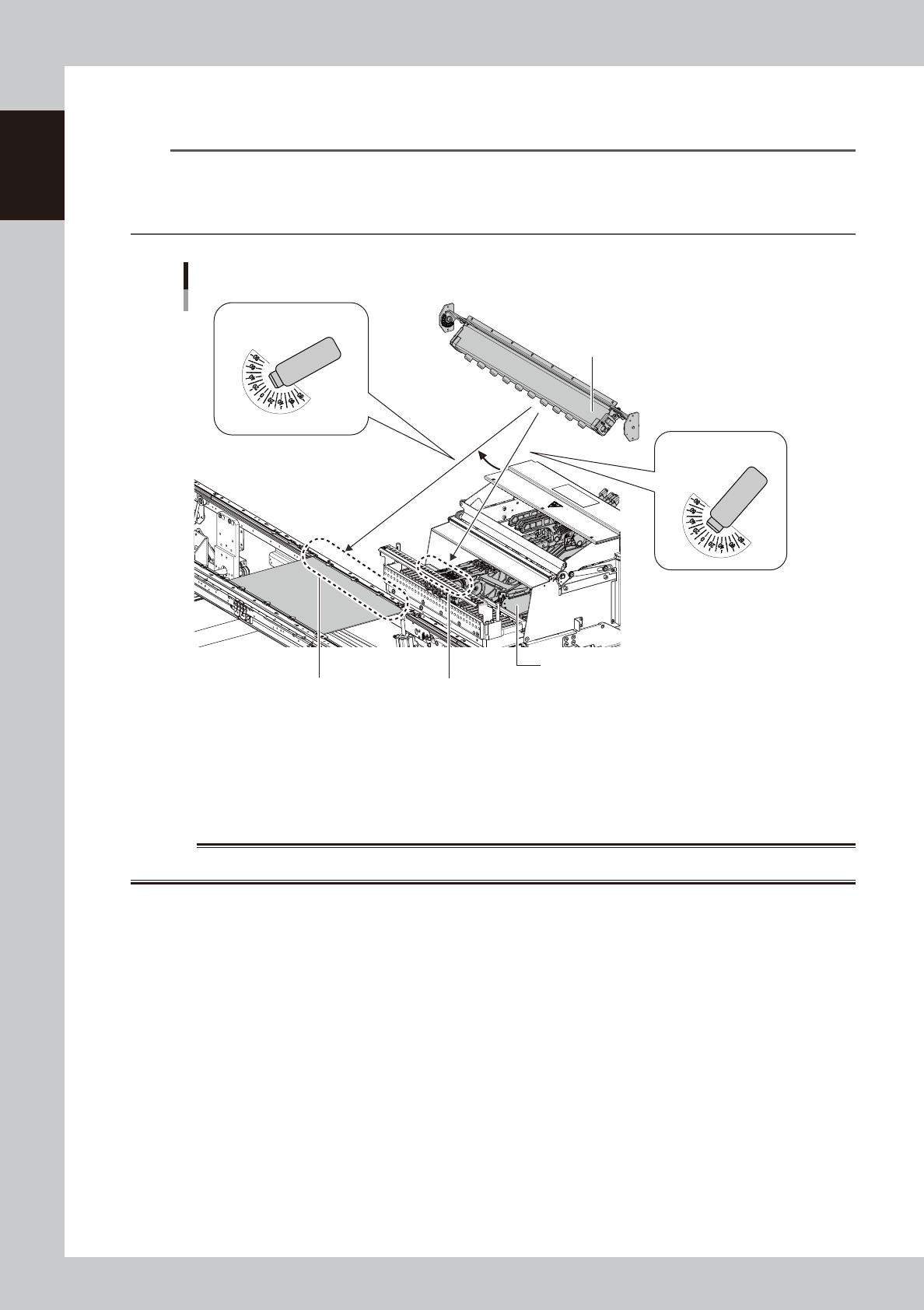
Procedure for changing ionizer installation angle
The ionizer installation angle can be changed with YSM20R.
TIP
Guideline for ionizer installation angle (in the case of the front ionizer)
0 degree : Near the feeder components pickup position
Upper 15 degrees : Near the conveyor frame on the side of operator at conveyor transfer position (for a machine
with the reference point on the operator side of the conveyor)
Ionizer installation angles
Ionizer
Tape feeder
15 degrees
Feeder component pick up positionConveyor frame (operator side)
Installation angle: 15 degrees
Installation angle: 0 degree
(when shipping)
23134-KMK-00
e
1
Power off the ionizer.
1. Press the emergency stop button and open the machine safety cover. This turns off the electrical
power supply to the ionizer.
2. Check that the green LED of “POWER” of the ionizer is off.
w
WARNING
DO NOT TOUCH THE IONIZER DISCHARGE METER.