YSM20R_YSM20WR_Ope_E.pdf - 第41页
1-8 1 Unit names and functions 2.2 Keyboard (option) An optional keyboard for operation and data editing, etc., can be added to the mac hine's configuration if desired. T he touchpad is used to mov e the cursor to t…
1-7
1
Unit names and functions
2. Operation panel and data input unit
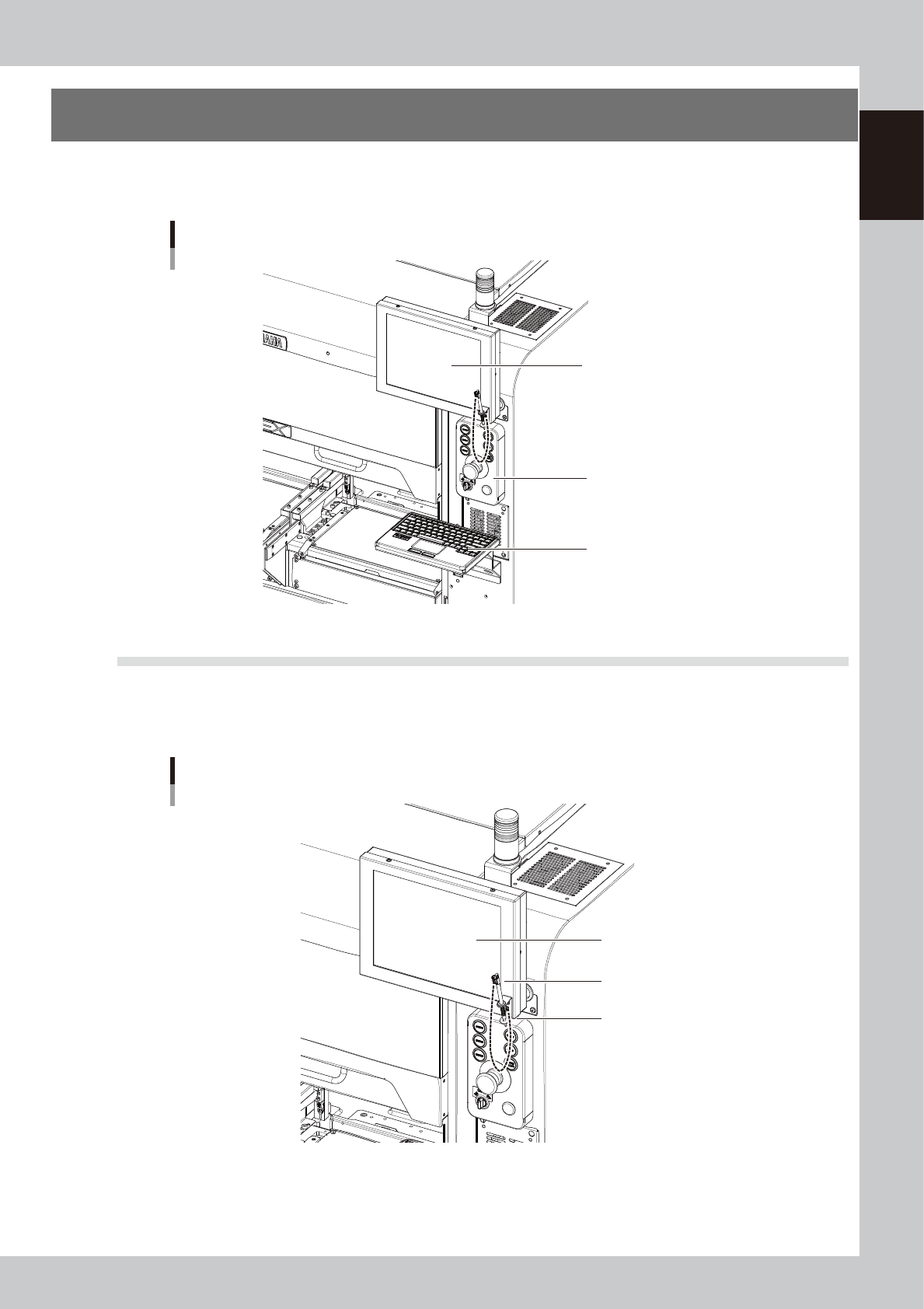
Operation panels and operation display screens for data inputs are provided at both the front and rear of
the machine. The functions of these units are explained below.
Operation panel and data input unit
Operation panel
Operation display
Keyboard (option)
23106-KMK-00
2.1 Operation display screen
Machine operation and data editing procedures are performed at the operation display screen (touch-panel
specifications). A touch pen is used to select the onscreen buttons and parameter items. Be sure to return the
touch pen to its holder when it is not in use.
Operation display screen
Holder
Touch pen
Operation display screen
(Touch panel)
23107-KMK-00
1-8
1
Unit names and functions
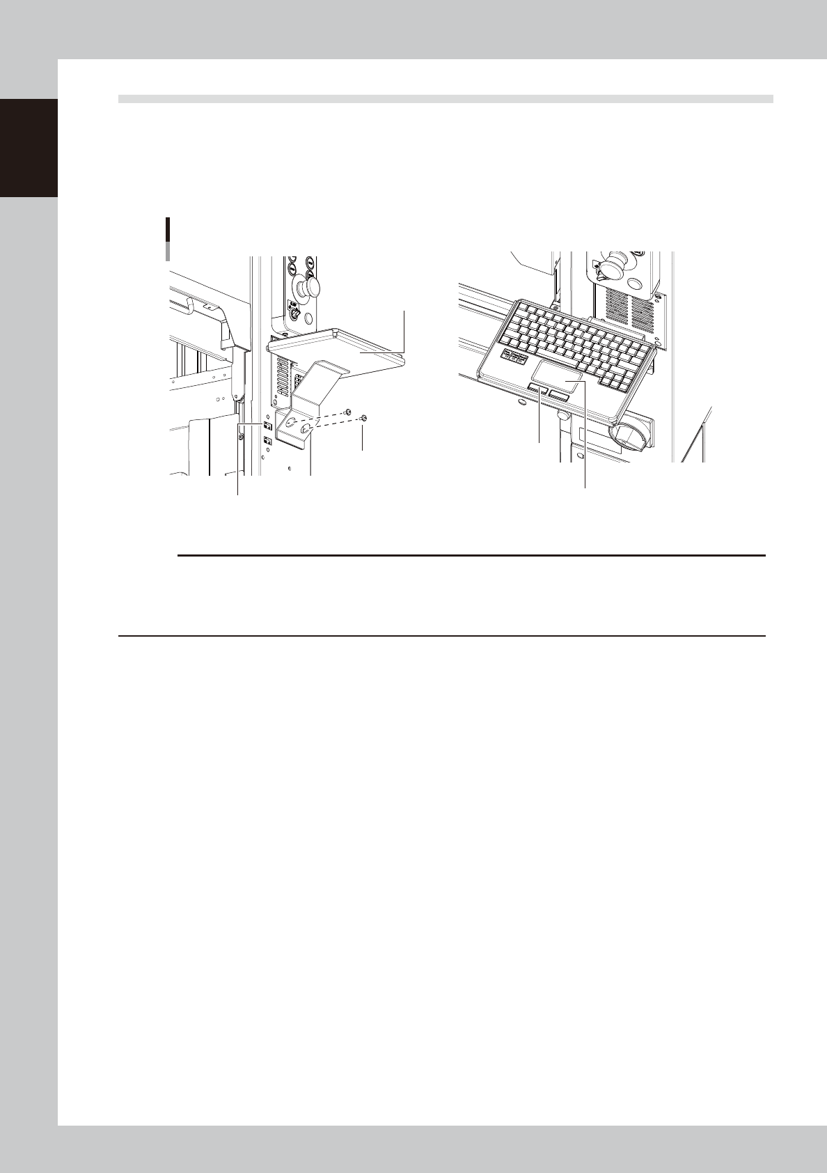
2.2 Keyboard (option)
An optional keyboard for operation and data editing, etc., can be added to the machine's configuration if
desired. The touchpad is used to move the cursor to the desired onscreen buttons and parameter items which
are then selected by pressing the left-click button (right-clicking is not available).
The keyboard is installed by mounting it on the keyboard holder, and then connecting its USB terminal to the
machine's USB port.
Keyboard
Left/right button
Touchpad
USB port for the keyboard connection
Keyboard holder
Keyboard holder
mounting screws
23108-KMK-00
c
CAUTION
The USB port for the keyboard connection shown in the figure above is dedicated to the keyboard. (Only keyboards
which do not require a -101 dedicated driver are supported.) Do not connect other USB devices to this port.
Moreover, connecting 2 or more keyboards will disable exclusive access control, and therefore stop keyboard
operation.

1-9
1
Unit names and functions
2.3 Operation panel buttons
The operation panel buttons are provided on the front and rear of the machine to run major commands
frequently used to operate the machine. Each button is lit while turned on. (The operation panel buttons light
up in the same colors specified by the signal light.)
Operation panel buttons
Lane switch
(For YSM20WR Dual-lane)
Operation panel buttons
Carriage clamp switch
Emergency stop button
Operation buttons
23109-KMK-10
n
Operation panel button functions
Button name Use the button to: OFF ON
ACTIVE
Enable other keys. (The front and rear
[ACTIVE] keys cannot be turned on
simultaneously.)
• After machine has started.
• The other table has access
rights to operate machine.
• Has access rights to
operate machine.
READY
Release emergency stop and turn the
servo on.
• SERVO OFF
(Motor power OFF)
• SERVO ON
(Motor power ON)
RESET
Stop automatic operation and return to
standby for board production.
• Machine is in normal operation
or stopped.
• Machine has been reset.
START (green)
Perform component placement
according to board data.
• Machine is stopped.
• Machine is in normal operation.
[Flash]
Pause or step operation
STOP (Red/White)
Interrupt automatic operation. (Press
START to resume operation.)
• Machine is in normal operation. • Error occurred.
ERROR CLEAR
(Yellow/Blue)
Stop buzzer sound and clear error
screen.
• Machine is in normal operation. • Error occurred.
EMERGENCY STOP
Trigger emergency stop. Turn to the
right to release it.
Switch Name Application
Carriage clamp switch
Turns the feeder exchange carriage and cATS10 carriage clamp ON/OFF.
This switch should be ON after setting the carriage in position, and OFF when detaching it. (cATS10 cannot
turn off the clamp.)
Lane switch Select the lane to be used. Select from the following 3 options: 1, 2, 1 and 2.
n
NOTE
The [ACTIVE] button is provided on both front and rear (option) panels, but cannot be turned on simultaneously. This
means that the [READY], [START], [ERROR CLEAR] and [RESET] buttons are enabled only when the [ACTIVE] key on the
same panel is turned on. (The [STOP] button can be used when the [ACTIVE] button is either on or off.)
The keyboard is enabled only when the [ACTIVE] key on the front panel is on.
c
CAUTION
Remove the feeder exchange carriage after the flashing of the clamp switch has stopped. If the feeder exchange
carriage is removed forcibly while the switch is flashing, this may cause malfunction.