YSM20R_YSM20WR_Ope_E.pdf - 第73页
1-40 1 Unit names and functions 5. Conveyor 5.1 Conveyor unit T he following describes the convey or unit that carries-in and clamps a board. n YSM20R Dual-stage type Board transfer direction Conveyor unit Dual-stage (Ri…
1-39
1
Unit names and functions
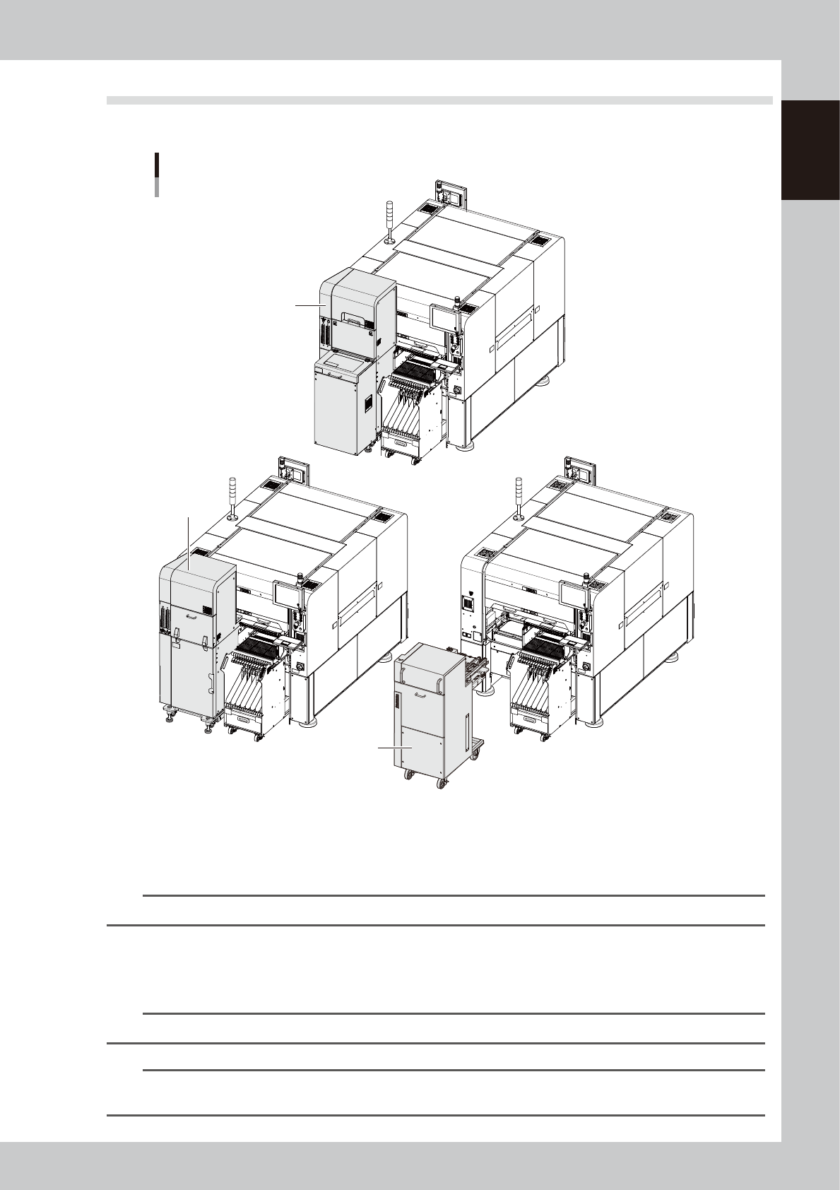
4.4 Tray component supply unit (option)
There are three types of tray component supply units, sATS30NS, sATS30 and cATS10.
sATS30NS, sATS30, cATS10
sATS30NS
sATS30
cATS10
23121-KMK-00
n
sATS30NS, sATS30
Supplies tray components with setting two magazines containing 15 pallets. With sATS30NS, components can be supplied
by a pallet even during production.
n
NOTE
sATS30NS can be installed to YSM20R, TypePV and YSM20WR.
n
cATS10
Supplies tray components with setting a magazine containing 10 pallets. This is the type of a carriage, which can be
exchanged with a feeder exchange carriage by users, who need to be trained.
n
NOTE
Refer to the option manuals for details of sATS30NS, sATS30 and cATS10.
n
NOTE
For changing the carriages between cATS10 type and feeder exchange carriage type, the training by YAMAHA or
YAMAHA distributors is necessary. Contact us in advance.
1-40
1
Unit names and functions
5. Conveyor
5.1
Conveyor unit
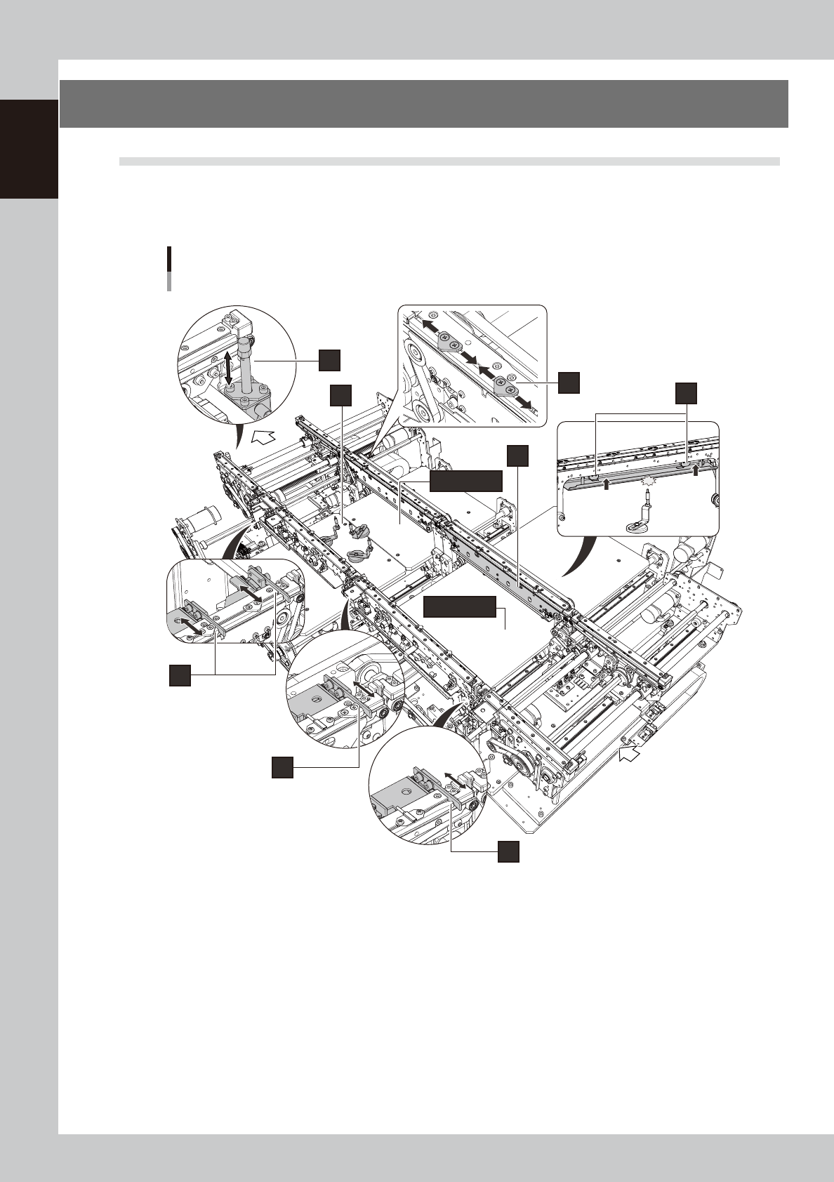
The following describes the conveyor unit that carries-in and clamps a board.
n
YSM20R Dual-stage type
Board transfer
direction
Conveyor unit
Dual-stage (Right-to-left flow example)
4
6
7
8
9
1
2
3
5 (Stage 2)
5 (Stage 1)
23122-KMK-00

1-41
1
Unit names and functions
1. Entrance stopper
If a board is on the mounting position already, other board carried into the conveyor waits at the position of the entrance
stopper.
2. Stage 1 main stopper
The board stopper for the mounting position of the stage 1. A board carried into the conveyor is in contact with the main
stopper, then it stops.
3. Stage 2 main stopper
The board stoppers for mounting position of the stage 2. There are two main stoppers for the stage 2, which are used
depending on the board sizes.
4. Exit stopper
If the machine in downstream doesn't demand a board, the mounted board waits at the position of the exit stopper.
5. Stage 1,2 Push-up plate
6. Push-up pins
Push-up pins are arranged on the push-up plate depending on the board to be mounted. When a board comes to the
mounting position, these pins secure the board by pushing it up from the bottom.
7. Board hold plate
8. Board clamp plate
When a board comes to the mounting position, the board clamp plate moves up. This clamps the board by pushing its
edges up against the board hold plates.
9. Pin push-up prevention sensor
This sensor stops the push-up plate moving up by detecting the push-up pin pushes up the conveyor frame when the
push-up pins are between the push-up plate and the conveyor frame.