YSM20R_YSM20WR_Ope_E.pdf - 第177页
2-74 2 Basic operation 5.3 Setting the pallet in the magazine 5.3.1 Setting the number of pallets to be stored T he sA TS30NS has two stages for the magazines at top and bottom. Each magazine can store up to 15 pallets w…
2-73
2
Basic operation
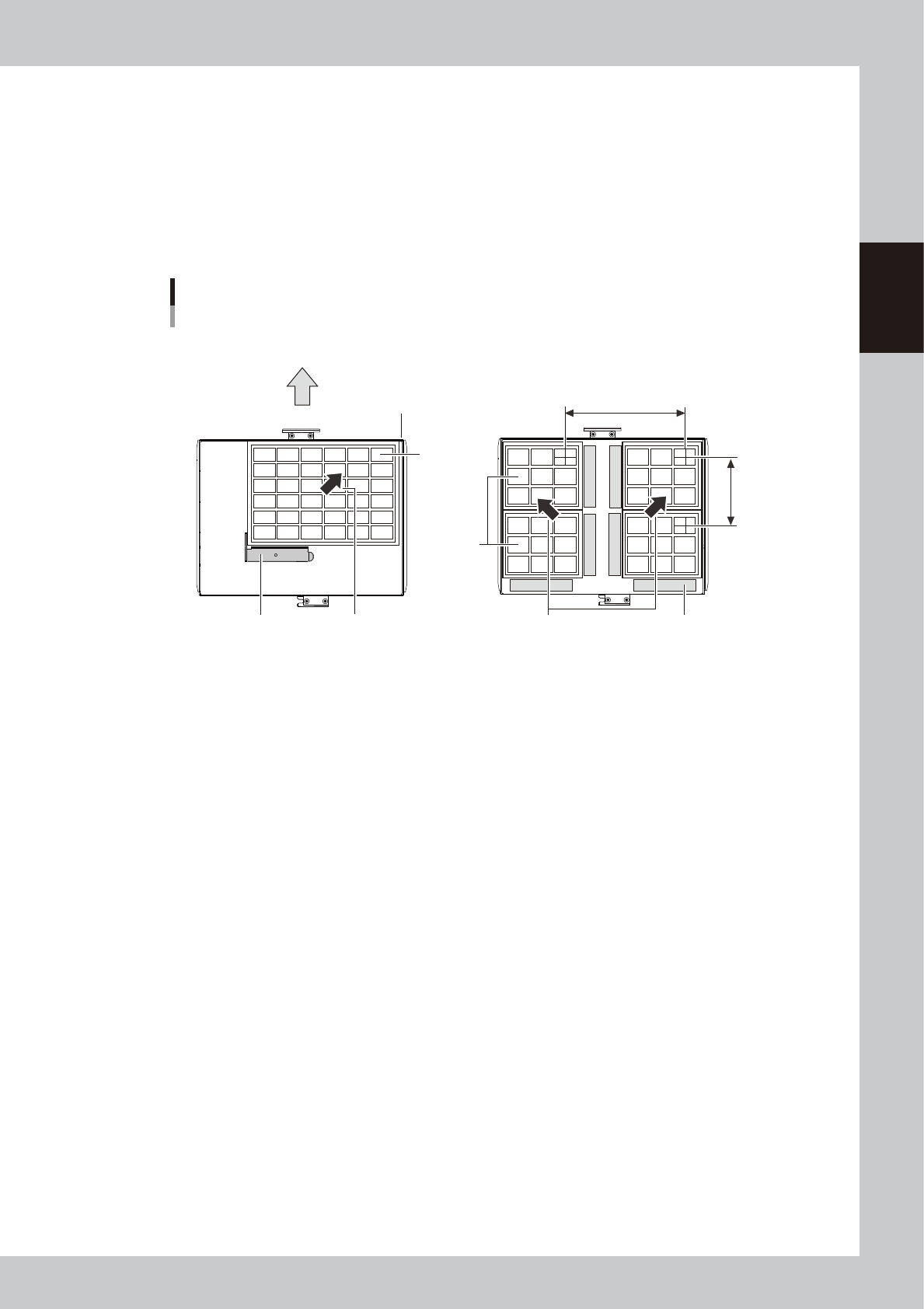
5.2.2 Setting the component trays on the pallet
More than one component trays can be set on one pallet. The procedure is described below.
1
Remove the tray clamp magnets.
2
Set the component tray on the pallet.
1. Set the component tray aligned with the corner of the pallet.
2. Hold the tray with the tray clamping magnet to clamp it.
Inserting direction
to sATS30NS
Align the component tray
with the corner of the pallet.
Align the component tray
with each corner of the pallet.
Clamping the component tray
Using one tray Using several trays
Tray pitch X
Tray
Tray
Tray pitch Y
Tray reference position
(pallet origin position)
Clamping magnetClamping magnet
23238-KMK-00
3
Check that the component tray is clamped.
Touch the tray to make sure that it is securely clamped by the magnet.
2-74
2
Basic operation
5.3 Setting the pallet in the magazine
5.3.1 Setting the number of pallets to be stored
The sATS30NS has two stages for the magazines at top and bottom. Each magazine can store up to 15 pallets
with 12.5 mm apart from each other. Up to 30 pallets can be stored at up and bottom magazines in total.
cATS30 also has two stages for the magazines for 15 pallets, but cATS10 has one stage for a magazine for 10
pallets.
If the thickness of the "component + component tray" on the pallet exceeds 8.5 mm, it is recommended to store
pallets in every other pallet stage spacing with 25 mm as shown below. In this case, up to 7 pallets can be
stored in sATS30NS. If the pallet pitch is 37.5 mm, up to 5 pallets can be stored.
n
NOTE
The highest component thickness (component + component tray) able to be mounted in this machine is 15 mm for
HM head unit or 28 mm for FM head unit.
2
4
6
8
10
12
14
3
6
9
12
15
Pallet storage examples
Number of pallets stored: 7
Number of pallets stored: 5
Number of pallets stored: 15
12.5 mm pitch
(Pallet Pitch Z: Normal)
25.0 mm pitch
(Pallet Pitch Z: x2)
37.5 mm pitch
(Pallet Pitch Z: x3)
23239-KMK-00
n
NOTE
The uppermost pallet is defined as pallet No.1. The number increases as the pallet set location goes down.
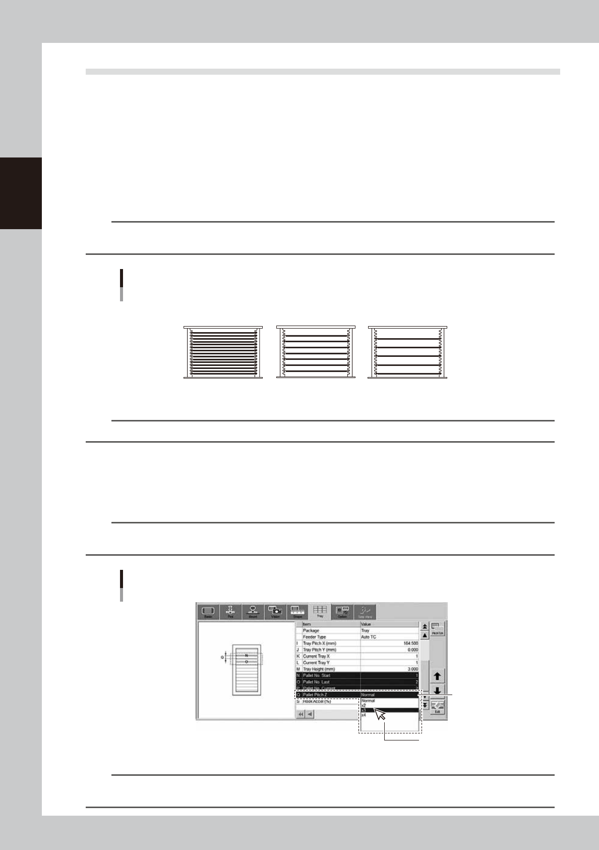
• Setting pallet pitch
The pallet pitch is set for each component at [Parts] - [Tray] screen.
Storing in every other rack : Set the "Pallet Pitch Z" to "x2".
Storing in every second rack : Set the "Pallet Pitch Z" to "x3".
n
NOTE
Setting the pallet pitch Z for each component enables to store the components with different pallet pitch in a same
magazine.
[Parts] - [Tray] tab screen
Pallet Pitch Z
Q. Pallet Pitch Z
Select from drop-down list.
24232-KMK-00
n
NOTE
See Surface Mounter (SMT) Programming Manual, chapter 3, "1.2 Auto/external tray changer” for the details of
creating board data for a tray component.

2-75
2
Basic operation
• Checking pallet pitch
Press [Machine] button to open "VmSpec" screen, then check the setting for the pallet pitch of the machine in "Setting"
- "Machine data" - "Tray changer" - "Position". Normally it is set with 12.5 mm as default.
n
NOTE
Normally the setting of the pallet pitch in "Machine setting" isn't changed.