YSM20R_YSM20WR_Ope_E.pdf - 第32页
Chapter 1 Unit names and functions Contents 1. Machine main unit 1-1 2. Operation panel and data input unit 1-7 2.1 Operation display screen 1-7 2.2 Keyboard (option) 1-8 2.3 Operation panel buttons 1-9 3. Head unit 1-10…
iii
About this manual
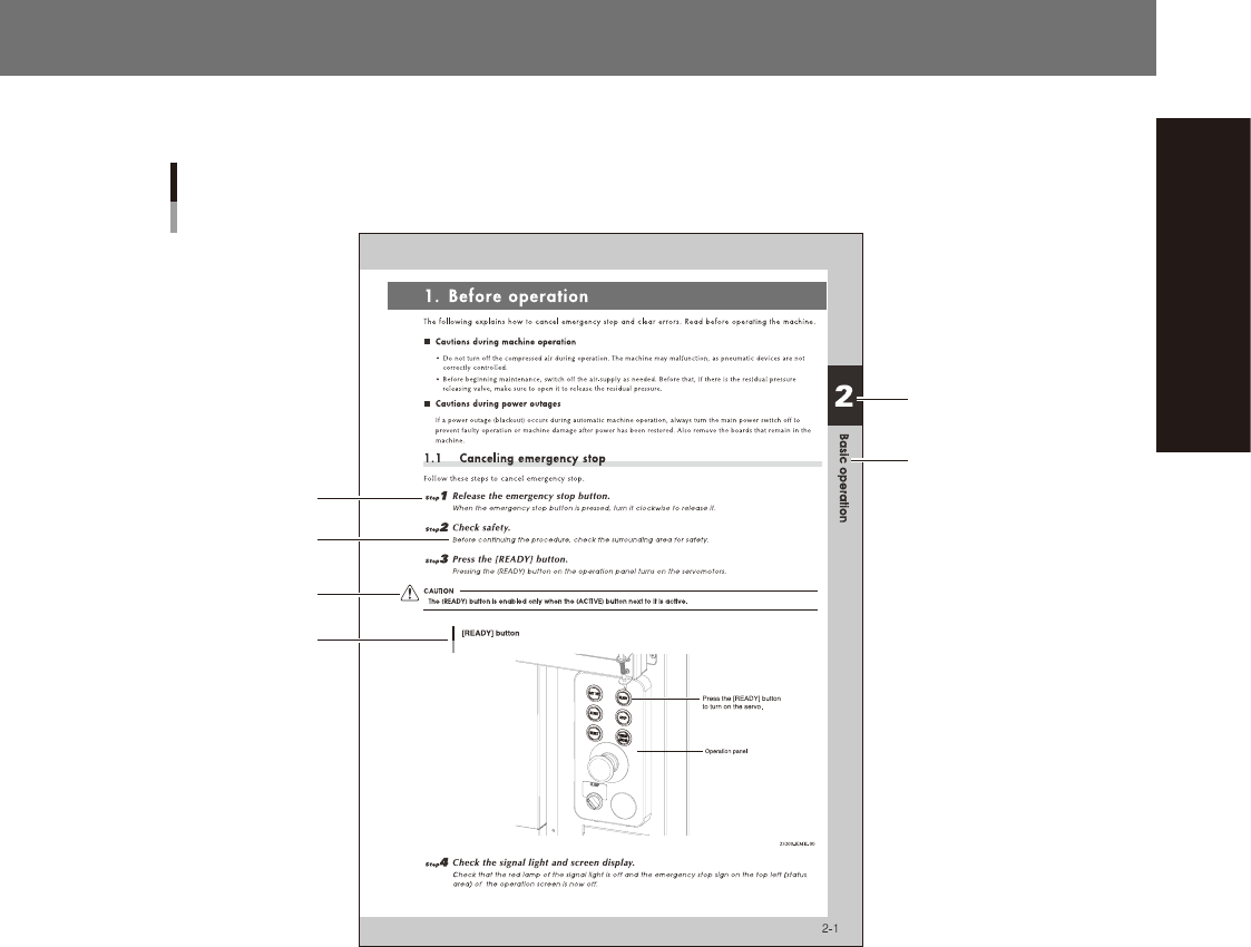
3. Page layout
The description below shows a typical page layout used in this manual.
Typical page layout
Step
Chapter number
Chapter title
Substep or
description of step
Figure, picture
or table caption
Note, Caution
or Warning
23001-KMK-00
n
Step
Describes the procedure for each operation.
n
Substep or description of step
Describes steps in detail.
n
Figure or table caption
This is the title of the figure or table and appears at the upper left.
n
Note, Caution or Warning
These are explained in detail in "Safety instructions".

Chapter 1 Unit names and functions
Contents
1. Machine main unit 1-1
2. Operation panel and data input unit 1-7
2.1 Operation display screen 1-7
2.2 Keyboard (option) 1-8
2.3 Operation panel buttons 1-9
3. Head unit 1-10
3.1 Component pick-and-place head 1-11
3.1.1 HM Head unit 1-11
3.1.2 FM Head unit 1-12
3.2 Nozzle types 1-13
3.2.1 HM Head / FM Head nozzles 1-13
3.3 Nozzle station (option) 1-14
3.3.1 HM Head nozzle station 1-14
3.3.2 FM Head nozzle station 1-15
3.4 Blow station 1-16
3.4.1 Shaft-blow function 1-16
3.4.2 Manual nozzle shaft blow procedure 1-17
3.4.3 Automatic nozzle shaft blow procedure 1-21
3.4.4 Shaft blow dump of very small components 1-24
4. Component supply section 1-25
4.1 Machine layout 1-25
4.2 Supply from fixed feeder bank 1-27
4.2.1 70-reel fixed feeder bank 1-27
4.2.2 Reel holder (option) 1-28
4.3 Supply from feeder exchange carriage 1-29
4.3.1 Feeder exchange carriage 1-29
4.3.2 Non-stop feeder change 1-32
Feeder removing conditions : 1. Setting "Skip Retry" 1-34
Feeder removing conditions : 2. Pressing [Feeder Remove] button 1-35
Feeder removing conditions : 3. Setting alternative component function 1-36
4.4 Tray component supply unit (option) 1-39
5. Conveyor 1-40
5.1
Conveyor unit 1-40
5.2 Sensor layout of conveyor unit 1-47
5.3 Board position in machine by conveyor type/board size 1-54

6. Recognition unit 1-56
6.1 Fiducial, Scan and Side-view camera 1-56
6.2 Side-view function (Scan camera / Side-view camera) 1-57
6.3 Multi-view cameras 1-58
7. Axis configuration 1-59
7.1 Head unit axis configuration 1-59
7.2 X/Y-axis and conveyor axis configuration 1-61
8. Other options 1-64
8.1 Coplanarity checker 1-64
8.2 Ionizer 1-65
8.3 UPS (Uninterruptible Power Supply) 1-68