YSM20R_YSM20WR_Ope_E.pdf - 第112页
2-9 2 Basic operation n "Mount compilation rate" on status area T he "Mount compilation rate" is displayed on the status area if the softw are version is 4.65 R1.000 or later . T he mount status on bo…
2-8
2
Basic operation
2. Operation screen and buttons
The basic configuration and operation methods of the operation screens are explained in this section.
n
NOTE
Because standard specification systems have no keyboard or mouse, all operations are performed from the touch-
panel. A dialog box displays at parameter input operations, and the desired operations and inputs can then be
performed with the touch-pen.
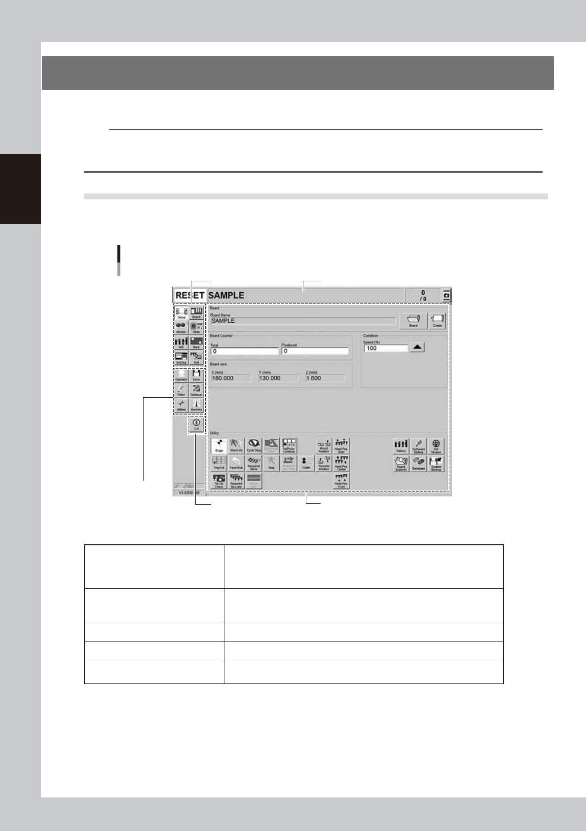
2.1 Basic configuration of operation screen
The operation screen consists of "Status area", "Main menu button area" and "Submenu button and parameter
area" as shown below.
Main menu button area 1
Main menu
button area 2
Main menu button area 3
Status area
Operation screen basic configuration
Setup screen ( Example of Dual-stage)
Submenu button and parameter area
24200-KMK-00
n
Area on screen
Status area
Displays the current machine status on the left end, the selected board name in
the middle, and the number of boards that have been produced on the right end.
(When producing with both lanes of dual-lane, the Board Name and Board
Counter of each lane are displayed in 2 rows.)
Main menu button area 1
Shows the main menu buttons used to operate the machine. The submenu
button and parameter area will change according to the selected main menu
button.
Main menu button area 2 Shows the menu buttons used to call up auxiliary functions of the machine.
Main menu button area 3 Shows the [Off] button to turn off the machine.
Submenu button and parameter area
Displays the submenu buttons and parameters for machine operation and data
setting. This area will change according to the selected main menu button.
2-9
2
Basic operation
n
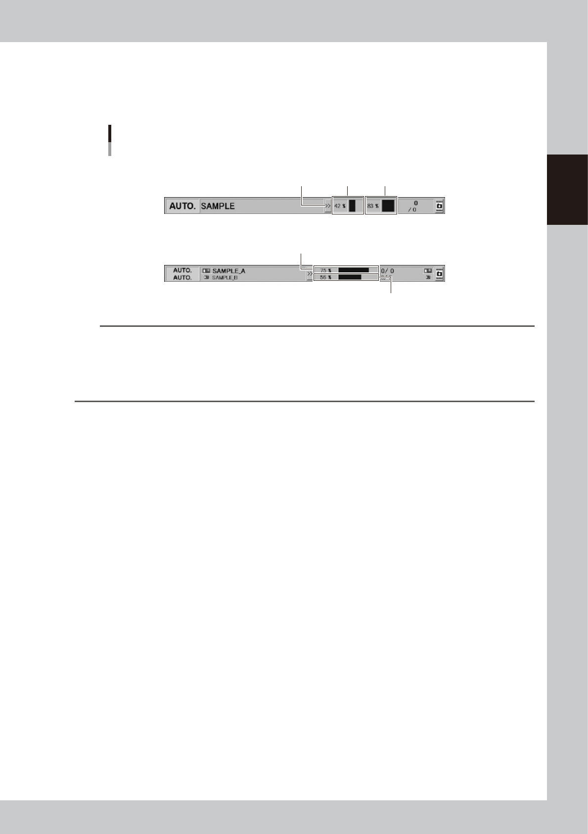
"Mount compilation rate" on status area
The "Mount compilation rate" is displayed on the status area if the software version is 4.65 R1.000 or later.
The mount status on board per stage/lane can be checked.
Note that [>>] / [<<] button on the status area hides/reveals the mount compilation rate.
Status area
Display of "Mount compilation rate"
Stage 1
Reveal/Hide
button
Stage 2
Lane 1
Lane 2
Dual-stage type
Dual-lane type
24236-KMK-00
TIP
The mount compilation rate is calculated with the following formula.
Mount compilation rate (%) = (The number mount is completed / The number of all mounts) × 100
Note that the mount point where the mounting is not performed due to the bad mark for instance is not included in
the mount completion rate. Therefore, the final mount compilation rate may not be 100%.
Additionally, the skipped mount point is not included in the calculation. If no mount data exists, "-" is displayed.
The mount compilation rate returns to 0% by reloading a board data.
2-10
2
Basic operation
n
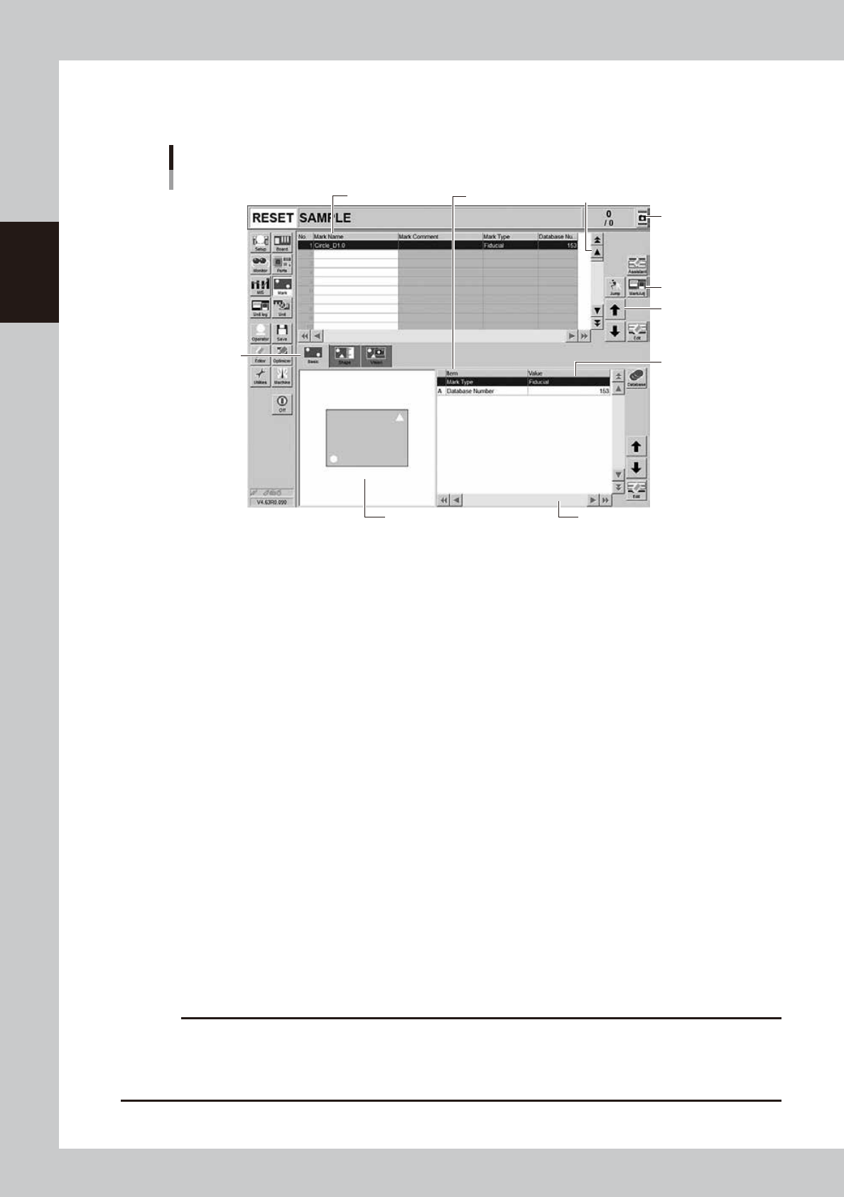
Buttons and parameter input boxes
Various types of buttons, selection tabs and parameter input boxes are used on the operation screen.
1
1
2
3
4
5
6
7
Operation screen basic elements
Mark screen
Parameter listData No. list
24201-KMK-00
1. Scroll bar and button (up/down, left/right)
Use the scroll bars or arrow buttons to see hidden items in the data No. list or parameter list.
2. Operation button
Press these buttons to open the next operation screen or dialog box.
3. Line up/down button
Use these buttons to move the cursor up or down through the data No. list or parameter list.
4. Parameter input box
Select, enter or edit parameters here. When the keyboard is used, double-click on a parameter input box to enter or edit
the data.
To operate the touch panel for data entry, press the corresponding “Edit” buttons on the right side of the screen to have
the edit box pop up.
5. Selection tab
Select this tab to switch the parameter input screen.
6. Assistant screen
Shows an illustration or information useful for parameter input or editing.
Alphabet characters shown in the parameter list and in the illustration on this screen correspond to each other.
7. Capture button
Captures the displayed image. The captured data (JPEG format) is stored in the D:\ScreenShot folder (maximum folder
size: approx. 10MB), with a file name consisting of the date and time.
When a USB memory device is inserted into the machine’s USB port and system backup is performed, a “ScreenShot”
folder is created in the root of the USB memory device to acquire the captured data stored in the machine. (The captured
data stored in the machine is moved to the USB memory device.)
c
CAUTION
• When saving data in a USB flash memory, make sure to use the USB flash memory designated by YAMAHA.
• If you specify the destination to save the data on the “Screen Shot Setting” window (Press the [Setup] – [Software
Setting] – [Information] – [Screen Shot Setting] buttons), the captured data cannot be saved in the USB flash memory
even by performing System backup.