YSM20R_YSM20WR_Ope_E.pdf - 第37页
1-4 1 Unit names and functions n USB flash drive por t Use this USB flash drive port w hen making a data backup or upgrading the software v ersion. USB flash drive port USB flash drive port Keyboard port Keyboard (option…
1-3
1
Unit names and functions
n
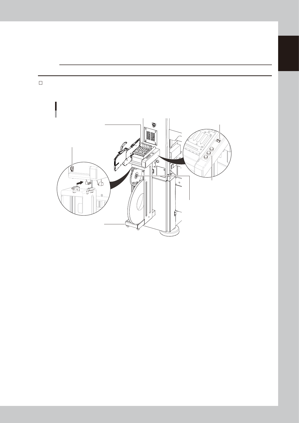
Safety cover
This cover must be closed during operation. If opened, emergency stop is triggered.
n
Power switch
Turns on or off the power to the machine. The power is on when turned to the right.
c
CAUTION
Wait about 2 seconds when powering on the machine after powered off it.
Set-up station (option)
This is used for setting component tapes in feeders and for changing the feed pitch.
Set-up station
7-inch tape reel holder
Guide rail
Display (Pitch indication)
Panel buttons
(Pitch switching)
15-inch tape reel holder
Power signal connector
23102-KMK-00
1-4
1
Unit names and functions
n
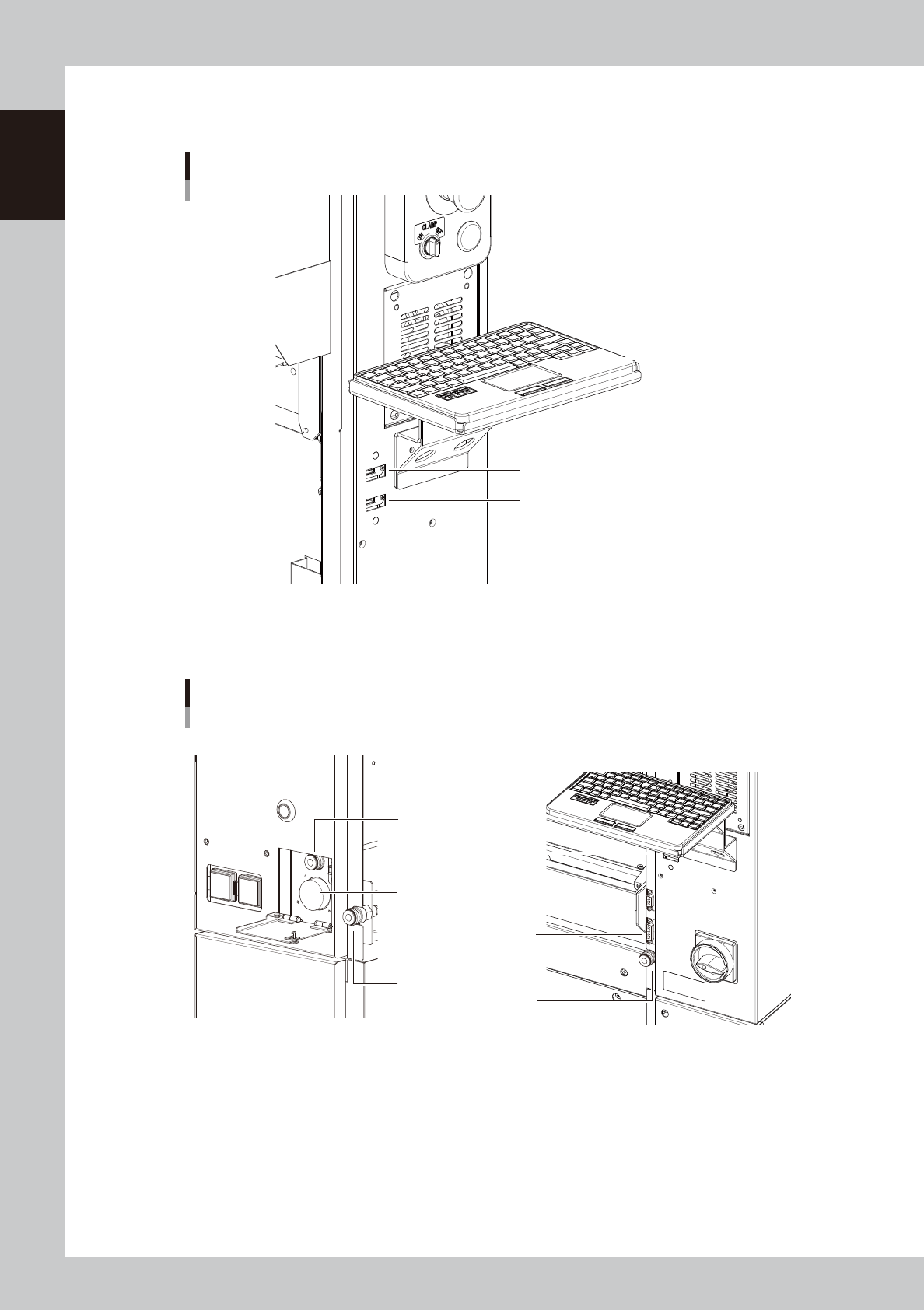
USB flash drive port
Use this USB flash drive port when making a data backup or upgrading the software version.
USB flash drive port
USB flash drive port
Keyboard port
Keyboard (option)
23103-KMK-00
n
Other connection ports
These ports are used for option units.
Other connection ports
Air joint for cATS10
Connector for cATS10
Front right sideFront left side
Air coupler
Air coupler
Connector for FM head load
calibration
Connector
for dipping station
23104-KMK-00
1-5
1
Unit names and functions
n
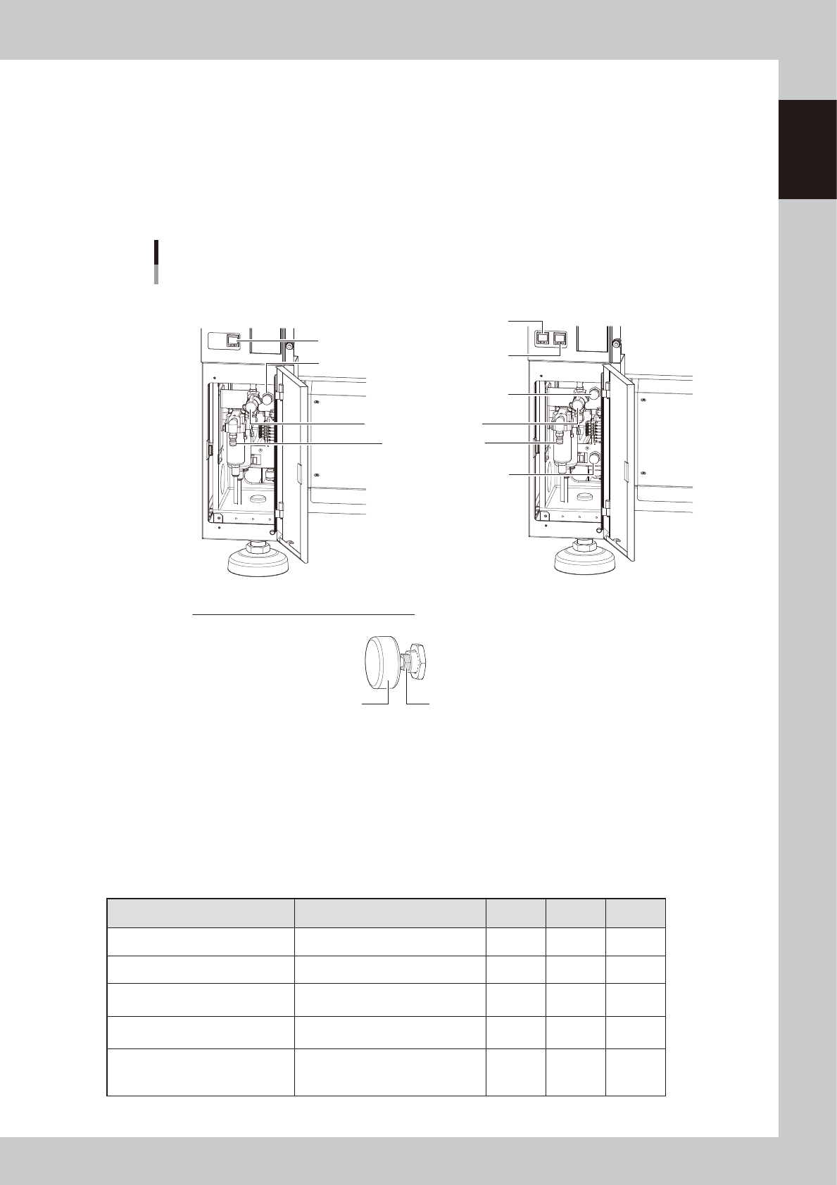
Pressure gauge
The set air pressure display on left side as viewed from the rear of the main unit (see the figure below).
• Set air pressure : 0.40MPa (0.39MPa to 0.41MPa)
• Interlock settings : lower limit 0.33MPa, upper limit 0.45MPa
n
Air connection port
The air hose from the air source is connected here. The air supply/exhaust switch releases the machine's internal residual
pressure.
Sections for connecting air, pressure adjustment and indicator
For 1-beam For 2-beam
How to lock air pressure regulator handle
Turn clockwise the lock nut at the root of the handle with a wrench (8 mm) and secure it.
Tightening torque: 1 to 1.5 N·m
* After the lock nut has come into contact with the main body, turn it further by 15 degrees as a
guideline.
Handle Lock nut
Air supply/exhaust switch
Pressure gauge
(B table)
Pressure gauge
(A table)
Pressure gauge
Supply air connection
Air pressure regulator
(A table)
Air pressure regulator
(B table)
Air pressure regulator
23105-KMK-00
n
Signal light (with buzzer)
Indicates current operating conditions of the mounter with a green, yellow and red light, or green, white and blue light
explained below. (The color of the signal light when a buzzer sounds can be selected from two patterns).
The buzzer at the bottom of the signal light sounds if an error or abnormal condition occurs. (Turning the controller ring
to left and right beneath the signal light allows to adjust the volume.)
Machine status Example Green
Red/
White
Yellow/
Blue
Warm-up or automatic operation ON ----- -----
Emergency stop ----- ON -----
System error
(with buzzer ON)
• Excessive current
• Secondary limit over
----- ON -----
Operation or board data error
(with buzzer ON)
• Pickup error, recognition error
• Data check error, etc.
----- ----- ON
Components cannot be used.
• Components run out.
Tray changer door is opened.
• Non-stop exchange carriage is off.
----- ----- Flashing