YSM20R_YSM20WR_Ope_E.pdf - 第226页
A-1 Appendix A1. Specifications n YSM20R/YSM20WR specifications Item Specifications Operating ambient temperature Function guaranteed: 15 to 35°C Accuracy guaranteed: 20 to 28°C Operating ambient humidity 20 to 80% (no c…

A-1
Appendix
A1. Specifications
n
YSM20R/YSM20WR specifications
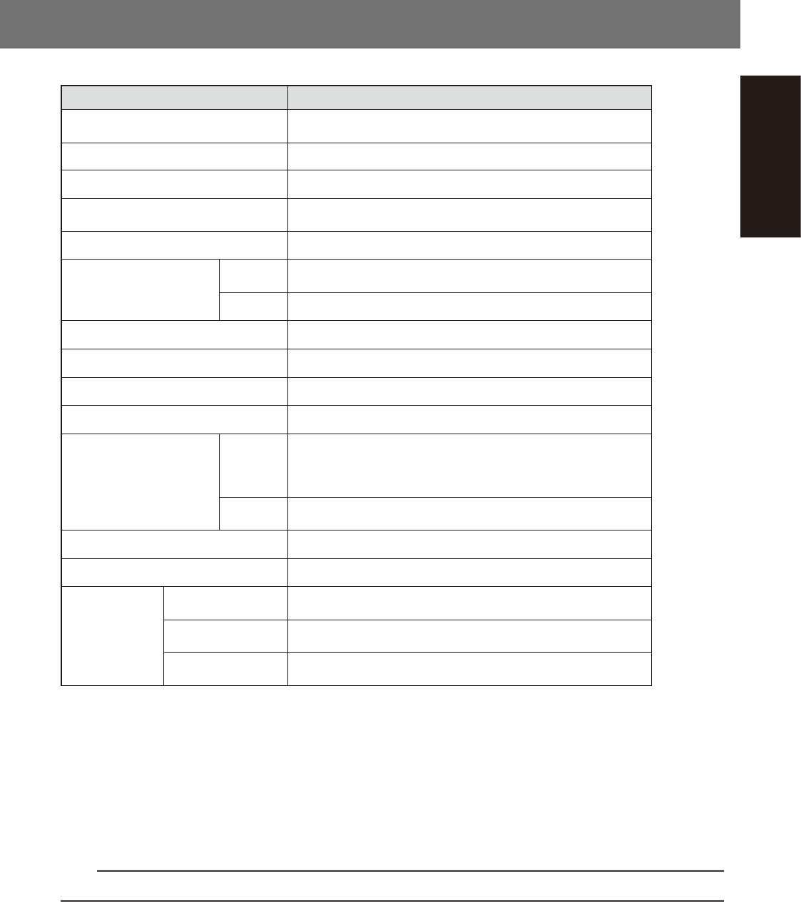
Item Specifications
Operating ambient temperature
Function guaranteed: 15 to 35°C
Accuracy guaranteed: 20 to 28°C
Operating ambient humidity 20 to 80% (no condensation), optimal range: 50 to 60%
Noise level Under 78dB
Power requirement (voltage and frequency) 3-phase AC 200/208/220/240/380/400/416 V +/- 10%, 50/60 Hz
Power capacity 10.4kVA
Average power consumption
YSM20R
TypePV: 1.9kW
TypeSV: 1.8kW
YSM20WR 1.9kW
Power cable (conductor cross-section area) 6 mm
2
or more
Overvoltage category *
1
Category III
Pollution degree *
1
Degree 2
Supply air pressure *
2
0.45MPa or more
Air consumption (ANR) *
6
YSM20R
HM head (1-beam) : 130L/min (average); 290L/min (max.)
HM head (2-beam) : 240L/min (average); 340L/min (max.)
FM head (1-beam) : 80L/min (average); 280L/min (max.)
FM head (2-beam) : 140L/min (average); 320L/min (max.)
YSM20WR
HM head (2-beam) : 240L/min (average); 340L/min (max.)
FM head (2-beam) : 140L/min (average); 320L/min (max.)
Altitude 1000 m or less above sea level
Board transport height *
3
900 mm +/- 10 mm
Data
Number of mounting
points *
4
12,800 points
Number of component
types
255 types per board
Number of fiducial
marks *
5
128 sets per board
*1: Conforms to IEC60664-1.
*2: For air dryer. Cleaning air filters. To be dry. Set pressure to 0.40 MPa.
*3: Distance from the floor surface to the upper surface of conveyor belt.
*4: Decreases with the number of boards, blocks and fiducial marks.
*5: When using 2-point fiducial mode.
*6: If the machine is equipped with tray component supply unit (option), add the air consumption of 10 L/min (ANR)
for each.
If the machine is equipped with an ionizer (option), add the air consumption of 10 L/min (ANR) per ionizer.
n
NOTE
See specification sheets for more detailed information not listed above.

S-1
INDEX
Index
Safety instructions
Safety instructions
Cautions during power outages xvi
Cautions regarding ferromagnetic fields xvi
CE marking i
Handling batteries xx
Handling grease and oil xx
Handling heavy objects xx
Handling solvents xix
Handling the laser xix
Label positions iv
Locking out switches xv
Muzzle plate xviii
Operator and service personnel xv
Safety xiv
Safety message xxi
Warning labels ii
Adjusting board hold plate position 3-15
Air connection port 1-5
Axis 2-19
[Axis] button 2-16
Axis configuration 1-59
X/Y axis and conveyor axis configuration 1-61
B
Before operation 2-1
Block Skip function
[Block Skip] button 2-12,3-34
Blow station 1-16
[Board Clamp] button 2-18
Board clamping method 3-8
Board position in machine by conveyor
type/board size 1-54
Buttons and parameter input boxes 2-10
Buzzer 1-5
C
Carriage clamp switch 1-9
Changing conveyor width 3-9,3-10
Check cleanness on nozzle tips 3-25
Checking condition of clamping the
board 3-19
Clearing an error 2-2
Component supply section 1-25
Component tape feed pitch 2-56
Feeder setup 2-58
Confirming nozzles 3-24
Connection between machines 1-6
[Convey Board] button 2-17
[Convey In] button 2-14
Conveyor unit 1-40
YSM20R Dual-stage type 1-40
YSM20R Single-lane L = 360 mm type 1-42
YSM20R Single-lane L = 510 mm type 1-43
YSM20WR Dual-lane L = 360 mm type 1-44
YSM20WR Dual-lane L = 510 mm type 1-45
YSM20WR Single-lane (for transferring heavy
board) 1-46
Conveyor unit setup 3-8
[Convey Out] button 2-14
[Convey-out Stop] button 2-12,3-29
Coplanarity checker 1-64,2-41
[Current Nozzles] button 2-19
[Cycle Stop] button 2-12,3-29
D
Detaching component tape 2-68
Displaying the production monitors 2-22
Disposing of used carrier tape 2-64
Disposing of used cover tape 2-62
E
Edge clamp 3-8
Edge delamination (cover tape) 2-44
Emergency stop
Canceling emergency stop 2-1
Empty tape dust box 1-28,2-64
Ending production 3-29
[Entrance Stopper] button 2-18
Error screen 2-11
Exchanging magazine 2-78
Exchanging pallet 2-82
[Exit Stopper] button 2-17
F
Feeder exchange carriage 1-29
[Feeder Information] button 2-20
Feeder removing conditions 1-34
Feeder set position
Air connector 1-27
Harness connector 1-27,1-31
Power connector 1-27,1-31
[Feeder Setting] button 2-20
Flow from starting up machine to
production 3-1
H
Handling the pallet 2-71,2-73
Head unit 1-10
FM Head unit 1-12
HM Head unit 1-11
Head unit axis configuration 1-59
How to check the sensor addresses 1-48
I
Input/output signals between machines
1-6
Ionizer 1-65
Ionizer installation angle 1-66
K
Keyboard 1-8
L
Lane switch 1-9
[Lane switch] button 2-14
Laying out push-up pins 3-9
M
[Machine] button 1-21,3-26
Machine layout 1-25
Machine main unit 1-1
Names and functions of major parts 1-1
Main menu button area 2-8
Main stopper 3-11
[Main Stopper] button 2-17,3-11
Main switch 3-3
Manual conveyor operation 2-14,2-17
Manual feeder operation 2-20
Manual head operation 2-19
Manual I/O operation 2-21
Monitor
Alignment screen 2-28
Badmark screen 2-31
Fiducial screen 2-30
Force screen 2-34
Main screen 2-24
Nozzle health check screen 2-39
Pick Pos. 2-32
Pick Rate Warning screen 2-35,2-36
Production screen 2-22
Retry screen 2-29
Schedule task screen 2-38
Vision screen 2-26
[Monitor] button 2-22
Multi-view camera 1-58
N
Names of each section of magazine 2-72
Names of each section of pallet 2-71
Non-stop feeder change 1-32
[Nozzle Change] button 2-19
Nozzle health check 2-39
Nozzle shaft blow
Automatic nozzle shaft blow procedure 1-21
Manual nozzle shaft blow procedure 1-17
Nozzle station 1-14
Nozzle types 1-13