YSM20R_YSM20WR_Ope_E.pdf - 第191页
3-3 3 Flow fr om starting up machine to production 1.2 Star ting the machine Proceed as follows to start the mac hine. w W ARNING THE SIGNAL LIGHT LIGHTS UP WHEN THE MACHINE ST ARTS UP THE OPERA TION. THE GREEN LAMP IS O…
3-2
3
Flow from starting up machine to production
1.1 Pre-operation check
e
Check the following points before powering on the machine.
w
WARNING
BEFORE STARTING MAINTENANCE, MAKE ABSOLUTELY SURE TO POWER OFF THE MACHINE OR THE MACHINE IS IN THE
STATE THAT THE EMERGENCY STOP BUTTON IS PRESSED.
n
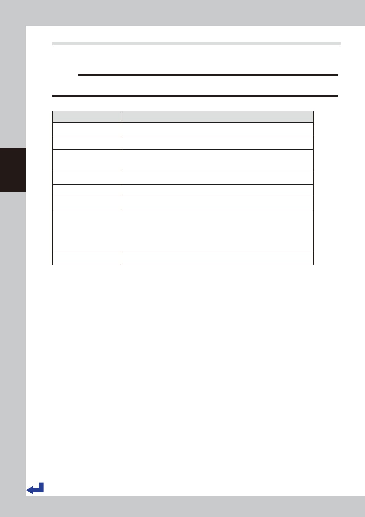
Pre-operation checklist
Check item Check point
Power supply
The specified power is connected to the power supply box located behind the front lower
right panel of the machine.
Safety cover The covers are closed.
Feeder Feeders are securely attached to the feeder plate and are not tilted.
No foreign objects are on the feeder and feeder plate. No used cover tape remains. The
feeder tail cover is closed.
Conveyor No chips or debris are on the conveyor.
No obstacles such as push-up pins are under the conveyor frame.
Head Each nozzle is correctly installed to the head.
Nozzle
The nozzle tips are not nicked, solder does not adhere to the nozzle tips, and nozzle
spring-action is smooth.
Tray component supply unit
(Option)
The pallet is correctly set up in place. No foreign objects are on the pallet
No pallet remains on the main body of the machine.
No pallet remains on the pallet station.(for sATS30 or sATS30NS)
Magazine door is surely closed.
The door switch is turned to "CLOSE".(for cATS10)The Magazine exchange switch is
turned to "RUN". (for sATS30 or sATS30NS)
Empty tape dust box
(Option)
No empty tape pieces are in the empty tape dust box.
3-3
3
Flow from starting up machine to production
1.2 Starting the machine
Proceed as follows to start the machine.
w
WARNING
THE SIGNAL LIGHT LIGHTS UP WHEN THE MACHINE STARTS UP THE OPERATION.
THE GREEN LAMP IS ON DURING OPERATION. THE YELLOW LAMP LIGHTS UP WHEN AN ERROR OR INTERLOCK OCCURS,
AND THE RED (OR WHITE) LAMP LIGHTS UP WHEN EMERGENCY STOP IS TRIGGERED.
NEVER PLACE ANY PART OF THE BODY IN THE HEAD MOVEMENT RANGE WHILE THE GREEN LAMP IS ON.
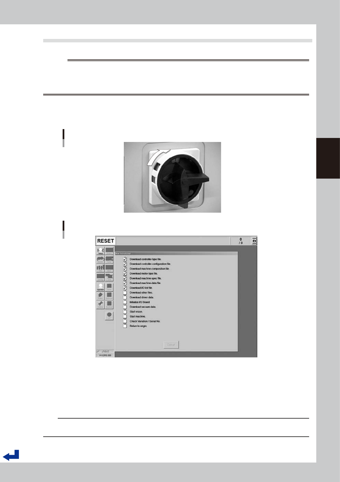
1
Turn the main switch ON.
Turn on the main switch at the front lower right of the machine, by turning it to the right. After the system
has started, the Initialization screen appears and the program necessary for machine operation is
loaded.
ON
OFF
Main switch
23302-KMK-00
Initialization screen
24301-KMK-00
2
Set the carriage to the machine.
When operating a machine with a carriage, see chapter 2, "4.1.3 Attaching the feeder exchange
carriage on the mounter" and set the carriage to the machine before performing return-to-origin.
3
Perform return-to-origin.
The “Return to origin” screen appears on the display. Press the [Ready] button and then follow the
instructions on the screen to perform return-to-origin.
n
NOTE
If the machine is not yet ready for return-to-origin operation, the return-to-origin operation on the setup screen can be
performed before going through the procedure according to "1.4 Warming up the machine" in this chapter.
3-4
3
Flow from starting up machine to production
1.3 Selecting the operator
Assign the operator who operates the machine.
Normally, register the operator names and operation authorities (and passwords, if necessary) in advance and
select the operator from those registered.
At the time of shipping, two operators or operator groups were registered - The “Administrator” (“A group of
administrators)” who have all the complete operation authorities and the “Default operator” (“A group of
default operators”) who have a fewer operation authorities.
TIP
Active menu buttons differ depending on the operation level setup. For example, when the machine is turned on with
the factory setup, the program starts up at an operation level called "Default Operator". This "Default Operator" level is
set to "Level 0" at the time of shipment to allow only basic operation items. This operation level can be changed as
needed. Operators and operation items can also be added and specified by setting the password and operation
level.
For more details, see “A2 Operator access control” in Appendix of the Surface Mounter (SMT) Programming Manual.
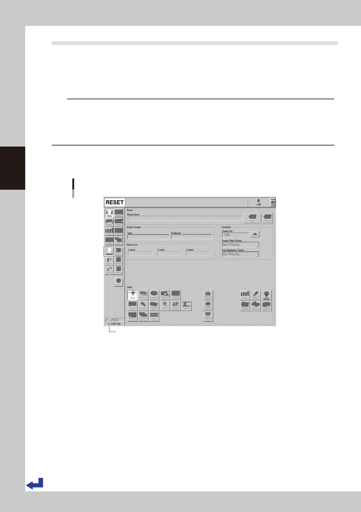
1
Press the [Operator] button.
The ID WINDOW screen appears for specifying the operator.
[Operator] button
[Operator] button
24302-KMK-00