YSM20R_YSM20WR_Ope_E.pdf - 第124页
2-21 2 Basic operation n Manual I/O operation 1 2 3 5 4 [Unit] – [I/O] screen 24211-KMK-00 Button name Function 1 Select output display group Select the output group for display in the "Output" status list. The…
2-20
2
Basic operation
n
Manual feeder operation
2
5
8
9
3
6
4
1 7
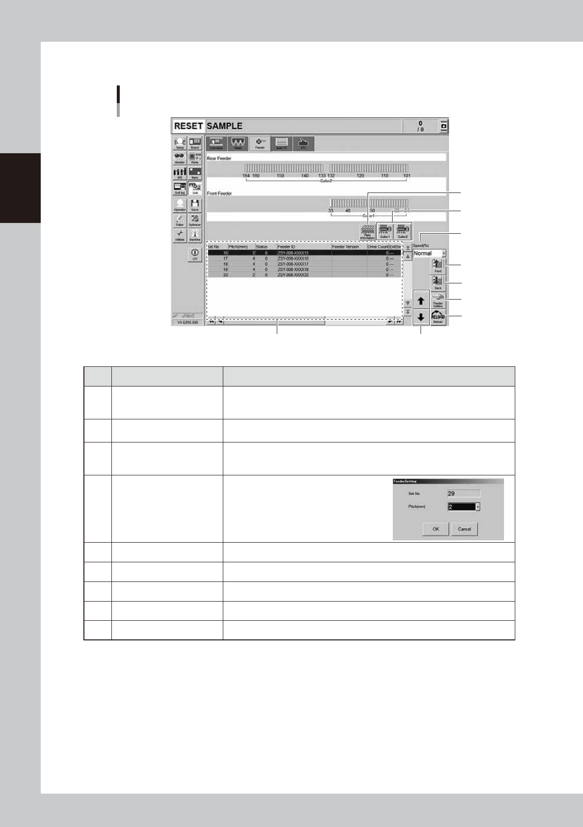
[Unit] – [Feeder] screen
24210-KMK-00
Button name Function
1 Feeder Information
Displays the information of the feeders set on the feeder plate.
The No. displayed in the "Status" column indicates the error code No. For error
details, refer to "SS Feeder User's Manual" and the "ZS Feeder User's Manual".
2 Feed
Feeds the tape on the feeder selected by the feeder information to one pitch.
Each time pressing this button advances the tape at the specified pitch.
3 Back
Moves the tape backwards by one pitch on the feeder selected by the feeder
information.
Each time pressing this button moves the tape backward at the specified pitch.
4 Feeder Setting
Pressing this button opens the feeder setting
dialog box that allows selecting a feed pitch
from 1 to 72 mm.
Set the feed pitch and press the [OK] button.
The set feeder pitch is stored in memory.
5 Speed Select the feed speed from the drop-down list with "Normal", 90,80, to 10%.
6 Reload Clears the feeder condition (memory) and reloads the setting.
7 Up/down arrows Moves the selected row up or down.
8 Cutter Opens or closes the tape cutter.
9 Plate Information Allows you to check the version of the plate board in the feeder plate.
2-21
2
Basic operation
n
Manual I/O operation
1 2
3
5
4
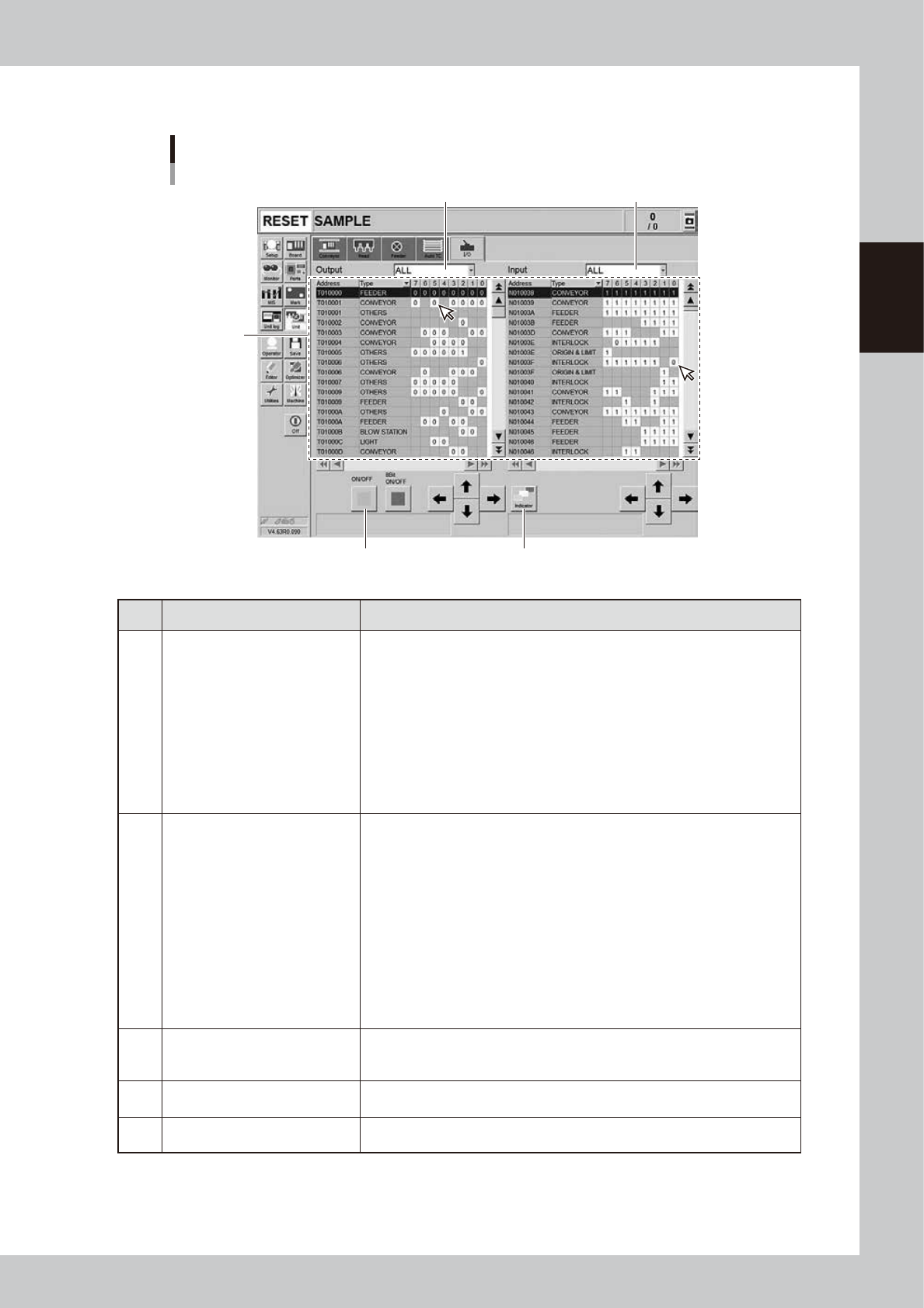
[Unit] – [I/O] screen
24211-KMK-00
Button name Function
1 Select output display group
Select the output group for display in the "Output" status list. The following
groups can be selected:
• FEEDER
• NZL STATION (Nozzle station)
• DUMP STATION
• BLOW STATION
• CONVEYOR
• HEAD
• LIGHT
• ATS
• OTHERS
2 Select input display group
Select the input group for display in the "Input" status list. The following groups
can be selected:
• INTERLOCK
• ORIGIN & LIMIT
• FEEDER
• NZL STATION (Nozzle station)
• DUMP STATION
• BLOW STATION
• CONVEYOR
• HEAD
• LIGHT
• ATS
• OTHERS
3 ON/OFF
As for the output signals, the valve actuation etc can be output forcibly as
needed. Click to select arbitrary signal and press the [ON/OFF] button. The
selected output signal turns ON or OFF.
4 Indicator
Lights up each unit of indicator such as a feeder, a carriage and a tray changer.
The mode of indication can be selected from “All”, “Individual” or “Sequence”.
5 Input/Output
Indicates the current status of sensors and valves.
I/O contents are displayed at the bottom of the screen with selecting by a cursor.
2-22
2
Basic operation
3. Displaying the production monitors
Press the [Monitor] button and check each monitor screen that appears to confirm the operation status
during the production. The monitor screens includes the [Main], [Vision], [Alignment], [Retry] etc. Select the
corresponding tab to check the ongoing mounting information.
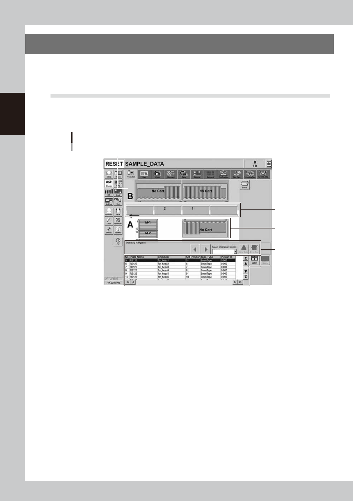
3.1 Production
This screen graphically shows the information of machines currently producing boards. The machine status
information such as errors that the machine is currently experiencing or work instructions appears on the lower
part of the screens.
1
2
3
4
Monitor: Production
Shows the machine rear as a colored background.
24212-KMK-00
1. Transfer status area
The board that the machine is currently working on is displayed in green.
If an error related to transfer has occurred or if a hazard prediction sensor is activating, the board is displayed in red.
2. Feeder status area
This area displays the feeder at the feeder set position that is registered on [Parts] - [Pick] tab - A: Feeder Set No. of the
board that the machine is currently working on. Nothing appears at the feeder set position where no components are
registered. The feeder is displayed in green where the feeder is correctly set up and ready for process. It is displayed in
red if the feeder is incorrectly set up or experiencing an error.
For machines equipped with a tray changer such as sATS30NS, the pallets setting status is displayed in this area.
3. Operating Navigation area (operating instruction message area)
• Operating Navigation instructions
This displays messages with countermeasures for handling errors, operating instructions or warnings at operating position
selected with the "Select Operating Position" drop-down list. When multiple errors occur, those items with the highest
priority for countermeasures are displayed in sequence. To switch to other instruction messages, press the left/right arrow
buttons.