YSM20R_YSM20WR_Ope_E.pdf - 第92页
1-59 1 Unit names and functions 7. Axis configuration This section describes the axis configuration and the axis movement direction on this machine. 7.1 Head unit axis configuration n HM head unit 10 1 1 10 1 10 ZB1 ZB10…
1-58
1
Unit names and functions
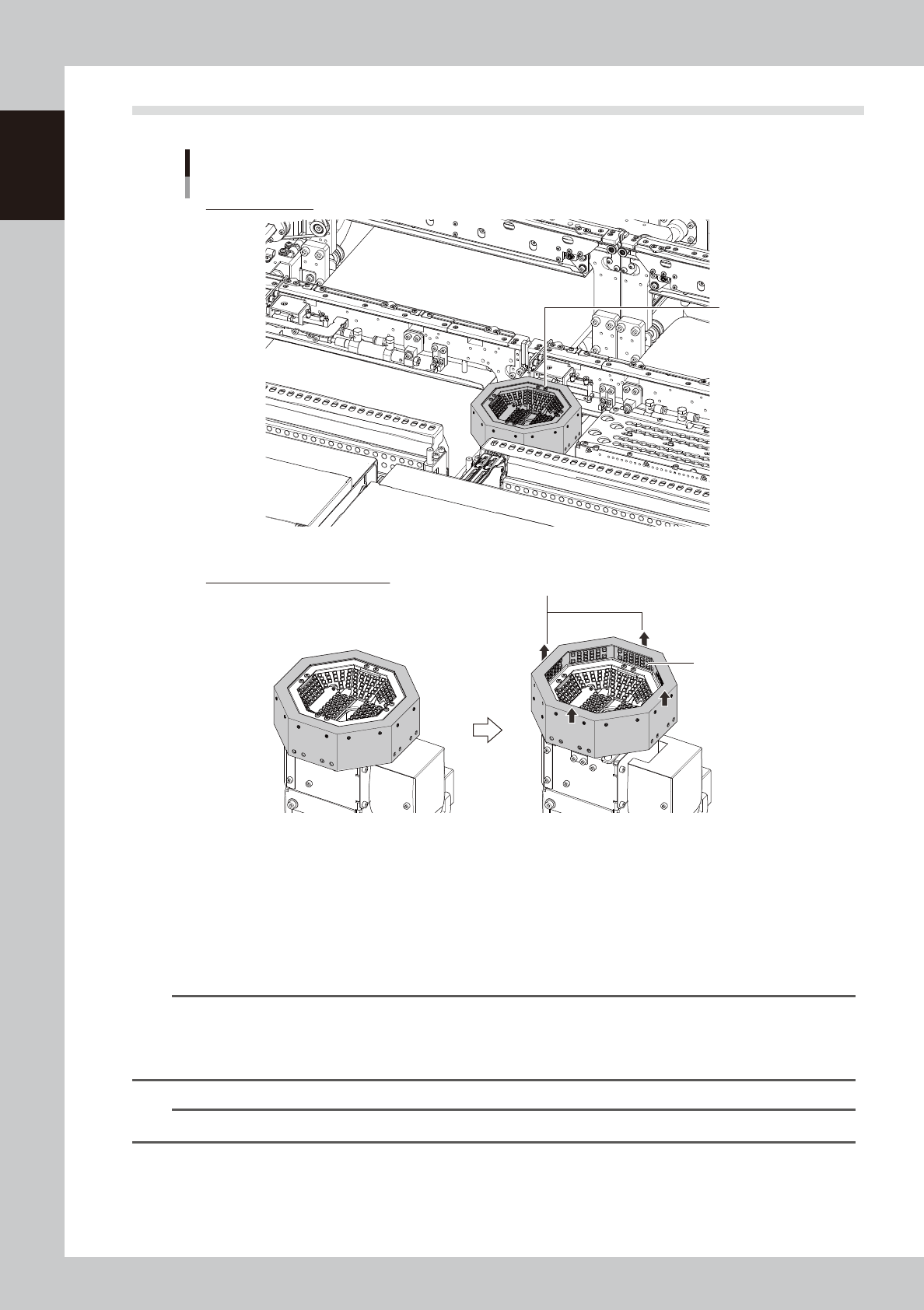
6.3 Multi-view cameras
Multi-view camera
Recognition unit
Multi-view
camera
Side lighting
Multi-view camera side lighting
The peripheral section of the multi-vision camera rises.
21127-KMK-00
n
Multi-view cameras
The multi-camera recognizes components when the components are mounted with a FM head unit or when the
components, which are too big for a scan camera to recognize, are mounted with a HM head unit. This is installed on
either or both of front and rear depending on the machine layout such as the head unit selection. To recognize the
components with "Side lighting" setting such as BGA and flip chips, the components are lighted by the peripheral section
of this camera rising up.
n
NOTE
The maximum sizes of components that scan camera can recognize are as below.
YSM20R TypePV : 12 mm square , 6.5 mm height
YSM20R TypeSV : 8 mm square , 6.5 mm height
YSM20WR : 12 mm square , 6.5 mm height
n
NOTE
See the “Programming Manual” for the setting details of the side lighting.
1-59
1
Unit names and functions
7. Axis configuration
This section describes the axis configuration and the axis movement direction on this machine.
7.1 Head unit axis configuration
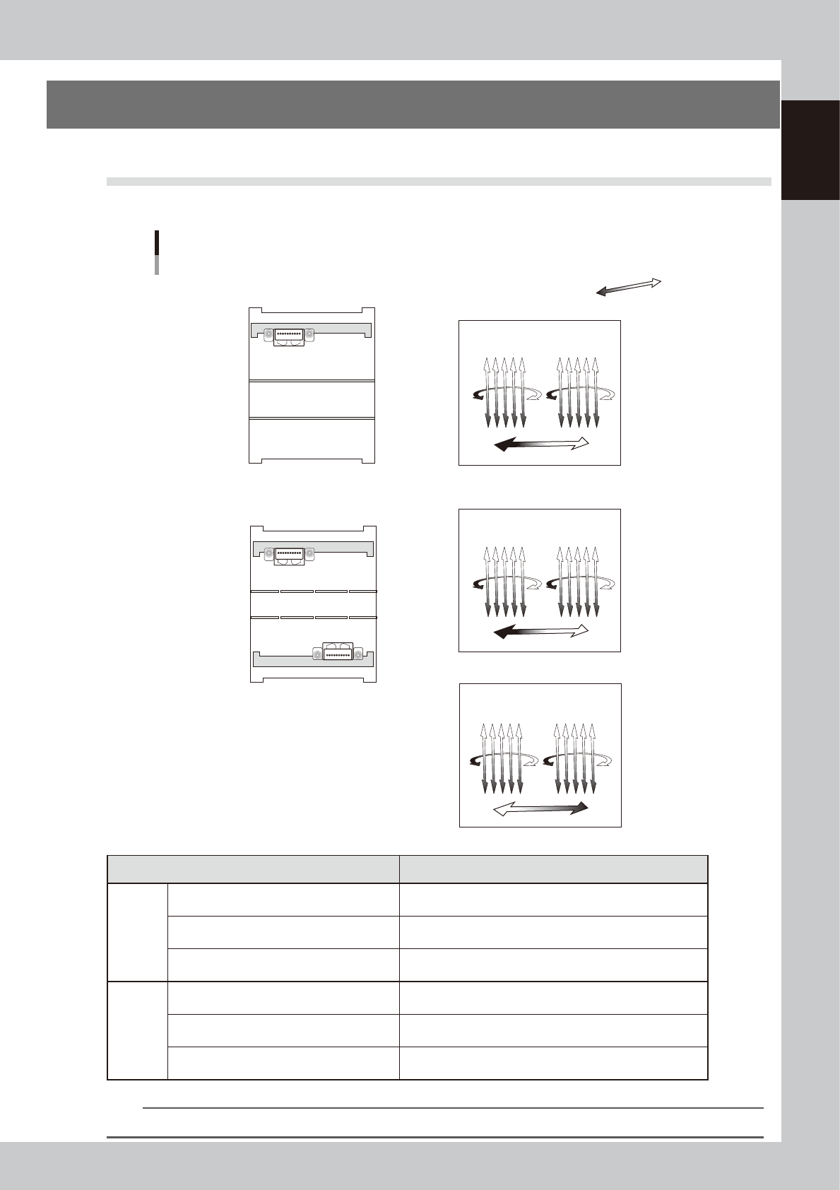
n
HM head unit
10
1
1
10
110
ZB1ZB10 ZB6 ZB5
ZA1ZA10 ZA6 ZA5
ZA10ZA1 ZA5 ZA6
A table
B table
Machine front
Machine front
Head axes configuration HM head unit
Example as viewed from the machine front
Plus direction
Minus direction
RA1 axis
RB1 axis
RA2 axis
RB2 axis
SCB axis
■ 2-beam
SCA axis
Head unit
B table Head unit
RA1 axisRA2 axis
SCA axis
■ 1-beam
A table Head unit
23128-KMK-00
Axis Function
HM
1-beam
ZA1-axis
→
ZA10-axis
Moves head picking up and mounting a component vertically.
The downward direction is positive.
RA1-axis
→
RA2-axis
Rotates five nozzle shafts by each motor RA1 and RA2.
The counterclockwise rotation is positive.
SCA-axis
Moves the scan camera.
The direction from No.1 head to No.10 head is positive.
HM
2-beam
ZA1-axis
→
ZA10-axis ZB1-axis
→
ZB10-
axis
Moves head picking up and mounting a component vertically.
The downward direction is positive.
RA1-axis
→
RA2-axis RB1-axis
→
RB2-axis
Rotates five nozzle shafts by each motor RA(B)1 and RA(B)2.
The counterclockwise rotation is positive.
SCA, SCB-axis
Moves the scan camera.
The direction from No.1 head to No.10 head is positive.
n
NOTE
On a 2-beam machine, the head unit at front is called "Table-A", and the head unit at rear is called "Table-B".
1-60
1
Unit names and functions
n
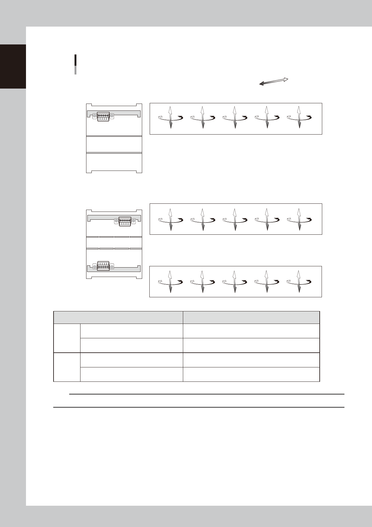
FM head unit
5 1
5 1
51
ZA1 axis
RA1 axis
ZA2 axis
RA2 axis
ZA3 axis
RA3 axis
ZA4 axis
RA4 axis
ZA5 axis
RA5 axis
ZB5 axis
RB5 axis
ZB4 axis
RB4 axis
ZB3 axis
RB3 axis
ZB2 axis
RB2 axis
ZB1 axis
RB1 axis
ZA5 axis
RA5 axis
ZA4 axis
RA4 axis
ZA3 axis
RA3 axis
ZA2 axis
RA2 axis
ZA1 axis
RA1 axis
Machine front
Machine front
A table
B table
Plus direction
Minus direction
Head axes configuration FM head unit
Example as viewed from the machine front
A table head unit
B table head unit
Head unit
A table
■ 1-beam
■ 2-beam
23129-KMK-00
Axis Function
FM
1-beam
ZA1-axis
→
ZA5-axis
Moves head picking up and mounting a component vertically.
The downward direction is positive.
RA1-axis
→
RA5-axis
Rotate the nozzle shaft of each head individually.
The counterclockwise rotation is positive.
FM
2-beam
ZA1-axis
→
ZA5-axis ZB1-axis
→
ZB5-axis
Moves head picking up and mounting a component vertically.
The downward direction is positive.
RA1-axis
→
RA5-axis RB1-axis
→
RB5-axis
Rotate the nozzle shaft of each head individually.
The counterclockwise rotation is positive.
n
NOTE
On a 2-beam machine, the head unit at front is called "Table-A", and the head unit at rear is called "Table-B".