YSM20R_YSM20WR_Ope_E.pdf - 第159页
2-56 2 Basic operation 4.1.4 Setting board data of component tape After completing setting up the feeder on the machine main bod y , set the tape feed pitch in the board data on the machine main bod y . 1 Check the compo…
2-55
2
Basic operation
2
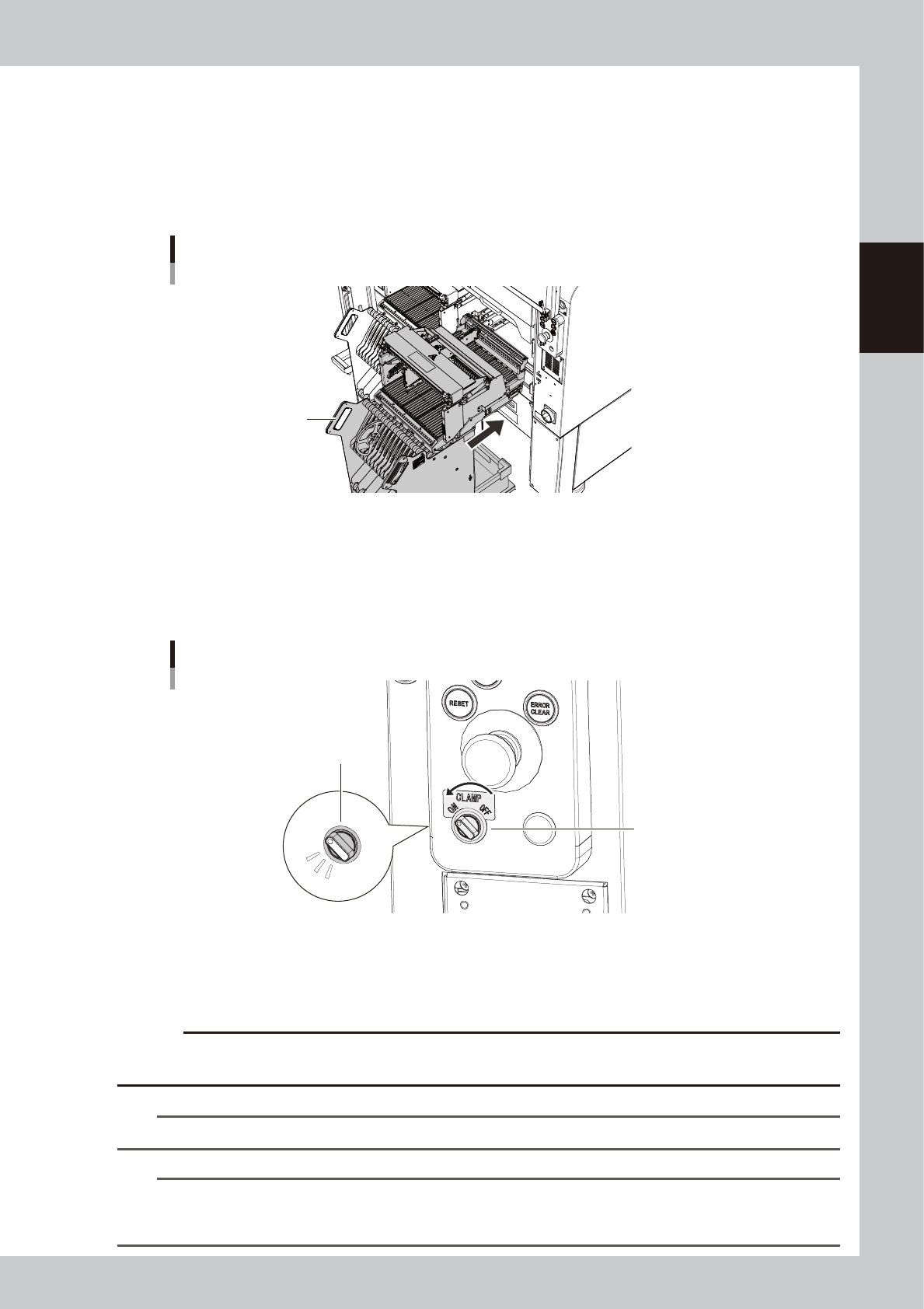
Put the carriage into the mounter.
1. (If SS feeder exchange carriage) Press the EMERGENCY STOP button and open the safety cover of
the machine.
2. Move the feeder exchange carriage in front of the position to attach the carriage.
3. While holding the carriage handle, insert it into the mounter straight.
4. Close the safety cover of the machine.(If SS feeder exchange carriage)
Put the carriage into the mounter
Handle
23221-KMK-00
3
Turn the clamp switch ON.
Turn the clamp switch corresponding the position where the carriage is inserted to left (ON), then the
indicator of the clamp switch starts blinking and the carriage clamp unit at the mounter side moves
down to clamp the carriage. After that, the communication is checked automatically between the
mounter, the carriage and the feeders.
Indicator blinks
Clamp switch
Clamp switch
23223-KMK-00
4
Check the clamp switch light is on.
After the communication check between the mounter, the carriage and the feeders are completed,
the switch indicator is changed lighting.
c
CAUTION
While the clamp switch is blinking, do not touch the carriage, the feeders and the mounter. The clamp unit moving
down might pinch hands.
n
NOTE
While the safety cover of the mounter is open, the clamp unit doesn't move down even with turning the clamp switch.
n
NOTE
There is the sensor called "forward end sensor(FDR FORWARD SENSOR)" at far left end of the carriage set position of
the mounter. When the carriage is inserted to far end, this sensor recognizes. When this sensor doesn't recognize the
carriage, the clamp units doesn't move down even with turning the clamp switch.
2-56
2
Basic operation
4.1.4 Setting board data of component tape
After completing setting up the feeder on the machine main body, set the tape feed pitch in the board data on
the machine main body.
1
Check the component tape feed pitch.
Check the component tape feed pitch prior to the operation.
2
Call up the [Parts] – [Basic] screen.
Read out the board data. Call up the [Parts] – [Basic] tab screen.
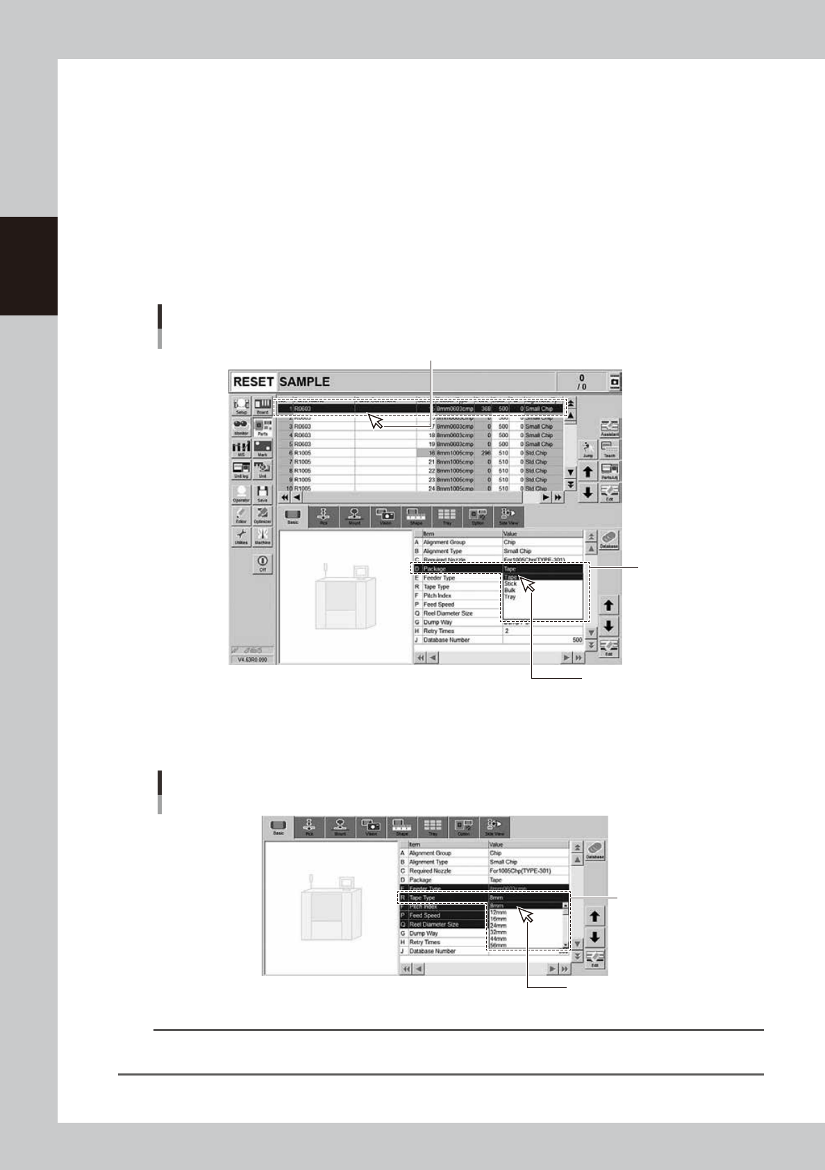
3
Specify the “Package”.
Select the components to specify the parameters for. Pull down “D. Package” and select “Tape”.
Setting up board data / Component tape
[Parts] - [Basic] tab
D. Package
Select “Tape”.
Select the components to specify the parameters for.
24226-KMK-00
4
Specify the “Tape type”.
Drop down “R. Tape Type” to select the type of component tape.
Setting up board data / Component tape
[Parts] - [Basic] tab
R. Tape Type
Select from the drop-down list.
24227-KMK-00
TIP
• Changing “D. Package” also changes “R. Tape Type”.
• The setting of “E. Feeder Type” is not provided.
2-57
2
Basic operation
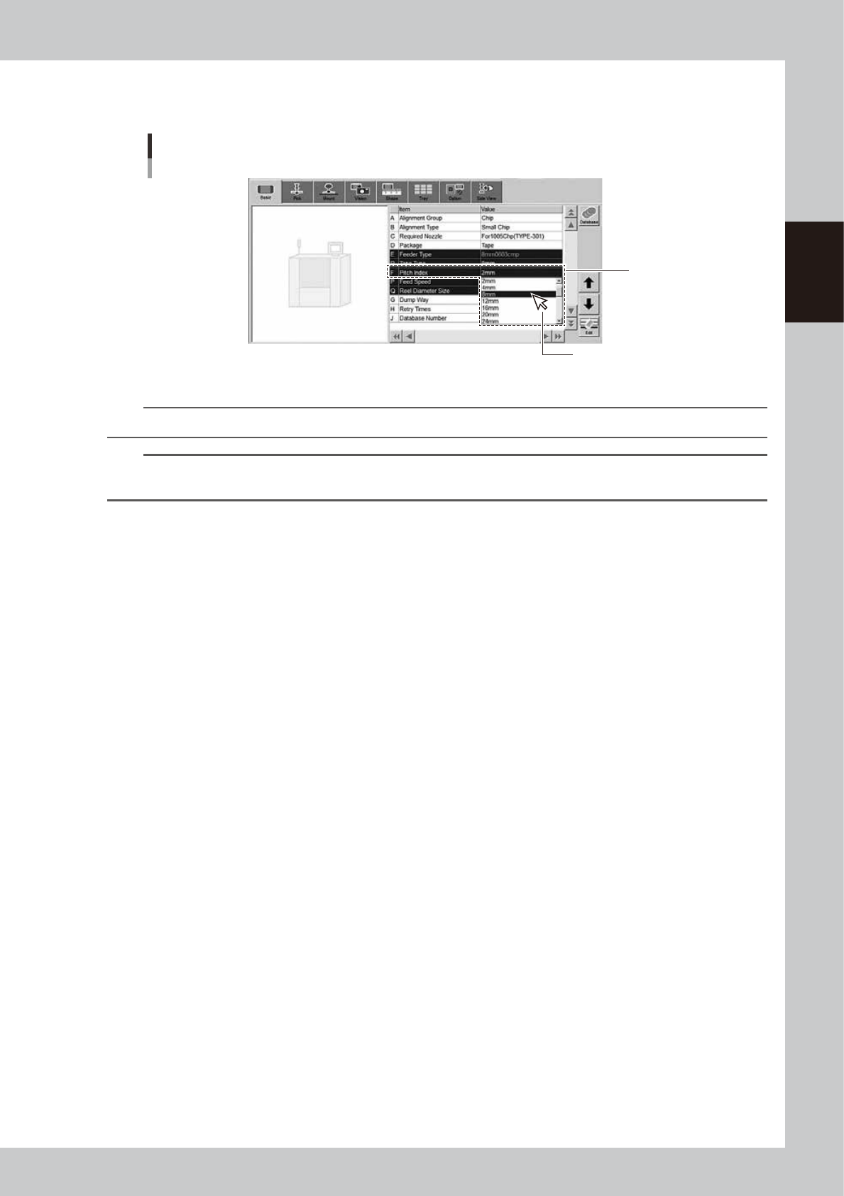
5
Specify “Pitch Index”.
Drop down “F. Pitch Index” to select the feed pitch according to the component tape to be used.
Specifying the Pitch Index
[Parts] - [Basic] tab
F. Pitch Index
Select from the drop-down list.
24228-KMK-00
n
NOTE
If “Feeder setup” is selected for "Reference of feeder pitch" on the Option Setting, “F. Pitch Index” does not appear.
TIP
See the “ZS Feeder User’s Manual” or the “SS Feeder User’s Manual” for the details of setting up the feeder board
data.