YSM20R_YSM20WR_Ope_E.pdf - 第43页
1-10 1 Unit names and functions 3. Head unit There are two kinds of head units that can be installed on this machine, high-speed general-purpose head (hereafter referred to as "HM head unit") and the head unit …

1-9
1
Unit names and functions
2.3 Operation panel buttons
The operation panel buttons are provided on the front and rear of the machine to run major commands
frequently used to operate the machine. Each button is lit while turned on. (The operation panel buttons light
up in the same colors specified by the signal light.)
Operation panel buttons
Lane switch
(For YSM20WR Dual-lane)
Operation panel buttons
Carriage clamp switch
Emergency stop button
Operation buttons
23109-KMK-10
n
Operation panel button functions
Button name Use the button to: OFF ON
ACTIVE
Enable other keys. (The front and rear
[ACTIVE] keys cannot be turned on
simultaneously.)
• After machine has started.
• The other table has access
rights to operate machine.
• Has access rights to
operate machine.
READY
Release emergency stop and turn the
servo on.
• SERVO OFF
(Motor power OFF)
• SERVO ON
(Motor power ON)
RESET
Stop automatic operation and return to
standby for board production.
• Machine is in normal operation
or stopped.
• Machine has been reset.
START (green)
Perform component placement
according to board data.
• Machine is stopped.
• Machine is in normal operation.
[Flash]
Pause or step operation
STOP (Red/White)
Interrupt automatic operation. (Press
START to resume operation.)
• Machine is in normal operation. • Error occurred.
ERROR CLEAR
(Yellow/Blue)
Stop buzzer sound and clear error
screen.
• Machine is in normal operation. • Error occurred.
EMERGENCY STOP
Trigger emergency stop. Turn to the
right to release it.
Switch Name Application
Carriage clamp switch
Turns the feeder exchange carriage and cATS10 carriage clamp ON/OFF.
This switch should be ON after setting the carriage in position, and OFF when detaching it. (cATS10 cannot
turn off the clamp.)
Lane switch Select the lane to be used. Select from the following 3 options: 1, 2, 1 and 2.
n
NOTE
The [ACTIVE] button is provided on both front and rear (option) panels, but cannot be turned on simultaneously. This
means that the [READY], [START], [ERROR CLEAR] and [RESET] buttons are enabled only when the [ACTIVE] key on the
same panel is turned on. (The [STOP] button can be used when the [ACTIVE] button is either on or off.)
The keyboard is enabled only when the [ACTIVE] key on the front panel is on.
c
CAUTION
Remove the feeder exchange carriage after the flashing of the clamp switch has stopped. If the feeder exchange
carriage is removed forcibly while the switch is flashing, this may cause malfunction.
1-10
1
Unit names and functions
3. Head unit
There are two kinds of head units that can be installed on this machine, high-speed general-purpose head
(hereafter referred to as "HM head unit") and the head unit for multi-kind components (hereafter referred
to as "FM head unit"). Up to two head units can be installed depending on the layout. The machine with
two head units called "2-beam" and the machine with one head unit called "1-beam" can be selected. The
combination of a HM head unit and a FM head unit is also applicable for a 2-beam machine.
n
NOTE
Refer to the specification sheets for machine layouts such as applicable combinations of head units.
51
101
110
110
5
1
Head unit
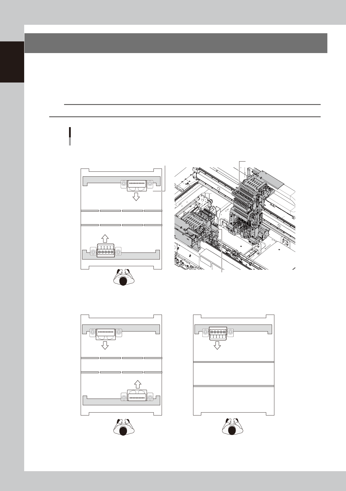
Examples of combinations of head units
HM head unit
Head No.
FM head unit
■ HM head units on both front and rear, 2-beam
■ FM head unit on front and HM head unit on rear, 2-beam
■ FM head unit, 1-beam
Front of machine
Front of machine
Front of machine
23110-KMK-00
1-11
1
Unit names and functions
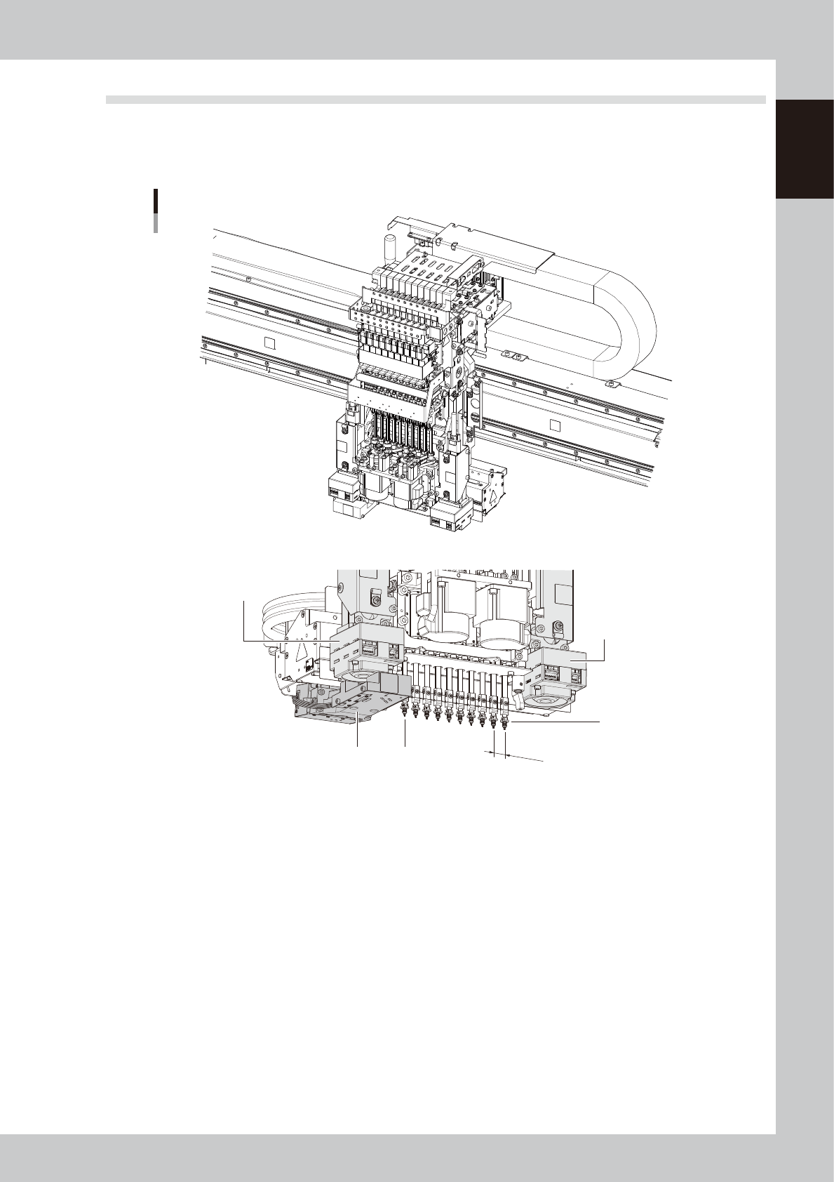
3.1 Component pick-and-place head
3.1.1 HM Head unit
The HM head unit has heads for picking up and mounting 10 components.
12mm
HM head unit
Scan camera unit
Fiducial camera
(Camera2)
Fiducial camera
(Camera1)
Head 10
Head 1
23111-KMK-00