YSM20R_YSM20WR_Ope_E.pdf - 第134页
2-31 2 Basic operation 3.7 Badmark T he [Badmark] screen shows the recognition results of badmarks such as "Board, Block" and "Local" badmarks. Monitor: Badmark 24218-KMK-00 • T able Select Select a h…
2-30
2
Basic operation
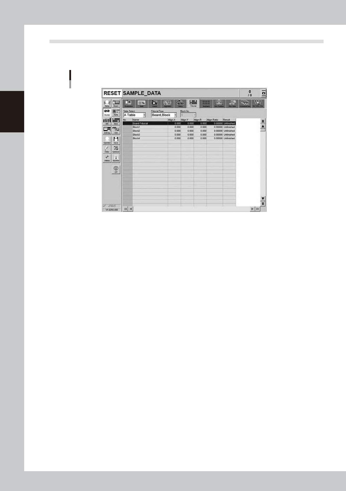
3.6 Fiducial
The Fiducial screen shows the results of recognizing fiducial marks such as “Board, Block”, “2 Point Local” and
“Point” and the correction result.
Monitor: Fiducial
24217-KMK-00
• Table Select
Select a head unit.
• Fiducial Type
Select the type of the fiducial mark such as "Board, Block", "2Point Local" or "Point".
• Align X, Y, R
Shows the differences between the fiducial mark recognition results and the input coordinate entered in the board data
with positive or negative values.
• Align Ratio
Shows the rate of expansion of the board, calculated by using the X, Y and R offset values.
• Result
Shows the recognition results as a "Pass" or "Unfinished ". The "Unfinished" message changes to "Pass" after the mark has
been recognized successfully.
2-31
2
Basic operation
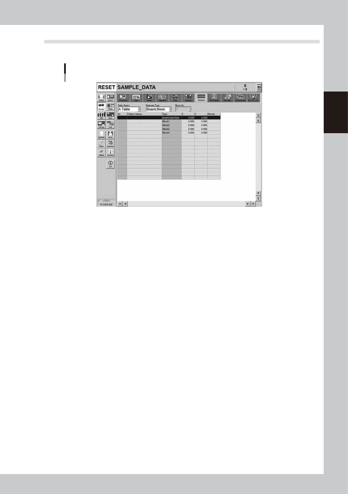
3.7 Badmark
The [Badmark] screen shows the recognition results of badmarks such as "Board, Block" and "Local" badmarks.
Monitor: Badmark
24218-KMK-00
• Table Select
Select a head unit.
• Badmark Type
Select the type of the badmark such as "Board, Block" or "Local".
• X, Y
Shows the board data input values (by taking block offset amount into account).
• Result
Makes an "OK" or "NG" decision based on the badmark recognition result.
OK: Failed in recognizing a bad mark: Means components are mounted.
NG: Succeeded in recognizing a bad mark: Means components are not mounted.
2-32
2
Basic operation
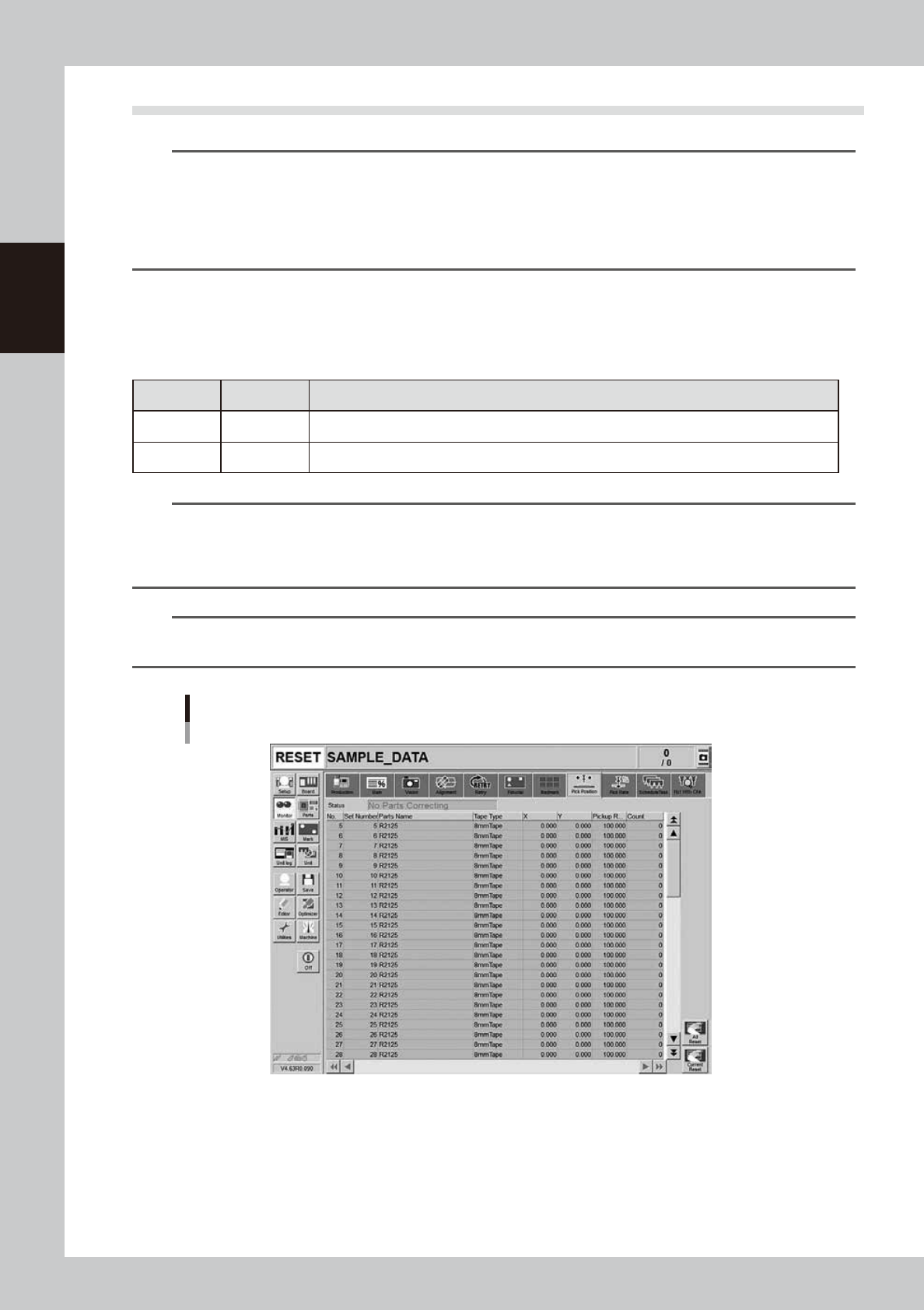
3.8 Pick Pos. (Pickup position offset)
n
NOTE
Pickup position offset function applies to the components satisfying the following conditions.
• The correct Mode on [Machine] - [Specification Information] - [Pick Position Specification] is set to either "Use"
or "Use with Feeder Correction".
• Component picked up with a nozzle that the "Available" on [Machine] - [Specification Information] - [Pick Position
Specification] is set to "Use".
• Component that "E: Pick Pos Correction" is set to "Use" on [Parts] - [Option] tab screen of the board data.
This screen appears when the pickup position offset function is used. This screen allows to check how the
pickup position of the object component (feeder) is corrected. If either the X or the Y correction amount
exceeds the warning zone or the error zone set up in the machine setting, the corresponding component in the
components list changes its color.
n
Display color
Color of row Status Description
Yellow Warning Exceeds warning level figure for each nozzle data set in pickup position offset specifications.
Red Error Exceeds error level figure for each nozzle data set in pickup position offset specifications.
n
NOTE
Warning generated: The machine generates an error message. The yellow lamp on the signal lamp tower flashes. The
machine, however, can continue the operation.
Experiencing error: The machine generates an error message when finishing producing one board. The machine
cannot continue the operation.
n
NOTE
The numerical values specified in the warning level and error level of the pickup position offset specification are
machine data setting items. Accessing such parameters require the administrator level of authority.
Monitor: Pick Pos. (Pickup position offset)
24219-KMK-00
• No.
Displays the component No. (Parts screen data No.).
• Set No.
Displays the feeder set No.
• Parts Name
Displays the component name.