YSM20R_YSM20WR_Ope_E.pdf - 第172页
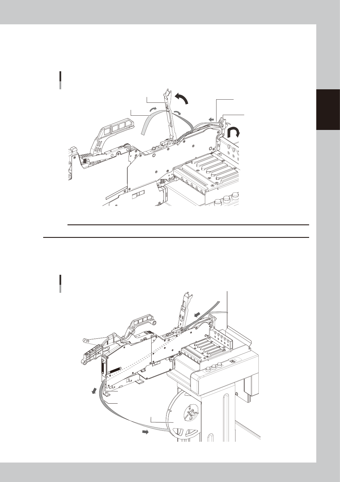
2-69 2 Basic operation 4 Lift the tape guide assembly . 1. Lift the tape guide front lever to the arrow direction and lift the tape guide assembly. 2. Pull out the cover tape from the tape guide assembly. 3. Pull out the…
2-68
2
Basic operation
4.1.8 Detaching component tape
n
NOTE
If a mounter is equipped with the set-up station, detach the component tape at set-up station.
1
Set the feeder on the temporary tape set station.
1. Set the feeder on the temporary tape set station (or the power station for the off-line setup).
2. Set the tape reel on the reel holder of the temporary tape set station.
2
Dispose of the used cover tape.
When the used cover tape remains in the cover tape box, cut it with the edge cutter inside of the tail
cover.
TIP
See "4.1.5 Disposing of used cover tape and carrier tape" in this chapter for the detailed procedure.
3
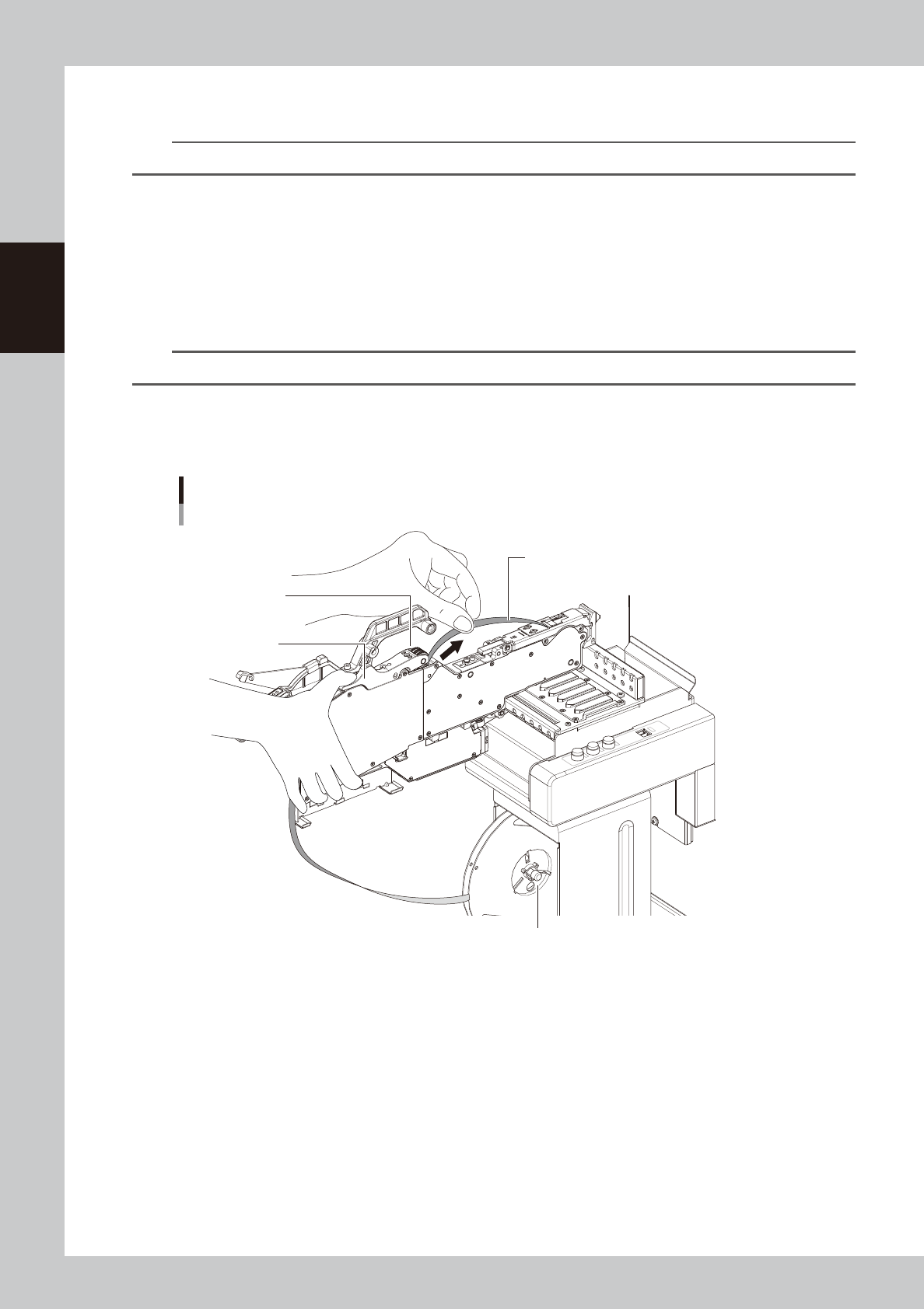
Pull out the cover tape.
Press the P/O lever assembly to make a clearance under the winding roller. Then pull out the cover tape
from the clearance.
Pulling out cover tape
Pull out cover tape.
P/O lever assembly
Winding roller
Reel holder of the temporary tape set station
23233-KMK-00
2-69
2
Basic operation
4
Lift the tape guide assembly.
1. Lift the tape guide front lever to the arrow direction and lift the tape guide assembly.
2. Pull out the cover tape from the tape guide assembly.
3. Pull out the carrier tape from the tape guide front lever.
Lifting tape guide assembly
Tape guide assembly
Tape guide front lever
Pull out carrier tape.
Pull out cover tape.
23234-KMK-00
c
CAUTION
Do not pull out the cover tape forcibly. Otherwise the tape guide assembly is deformed and pickup error may occur.
5
Pull out the component tape from ZS feeder.
1. Pull out the component tape from the insertion slot at rear of ZS feeder.
2. Rotate the tape reel to roll up the component tape.
Pulling out component tape
Component tape
Tape reel
Component tape insertion slot
23235-KMK-00

2-70
2
Basic operation
5
.
Preparing tray component supply unit
There are three types of the tray component supply units, sATS30NS, sATS30 and cATS10. The tray
component supply is described here with sATS30NS as a main example.
n
NOTE
Refer to each option manual for details of sATS30NS, sATS30 and cATS10.
5.1 Starting and ending the tray component supply unit
Starting and ending the tray component supply unit is all interlocked with the mounter operation.
When the mounter is powered on, the tray component supply unit is also powered on. When the mounter is
powered off, the tray component supply unit is also powered off.
Refer to "Chapter 3 Flow from starting up machine to production" for the procedure of powering on this
machine.