YSM20R_YSM20WR_Ope_E.pdf - 第215页
3-27 3 Flow fr om starting up machine to production 3 Set the “Nozzle T ip Cleanliness Check” . 1. Pull down the “Check Item” and select “Nozzle T ip Cleanliness Check”. 2. Provide the check boxes of the object nozzles (…
3-26
3
Flow from starting up machine to production
n
“Setting the Nozzle Tip Cleanliness Check”
The following describes how to set the “Nozzle Tip Cleanliness Check”.
1
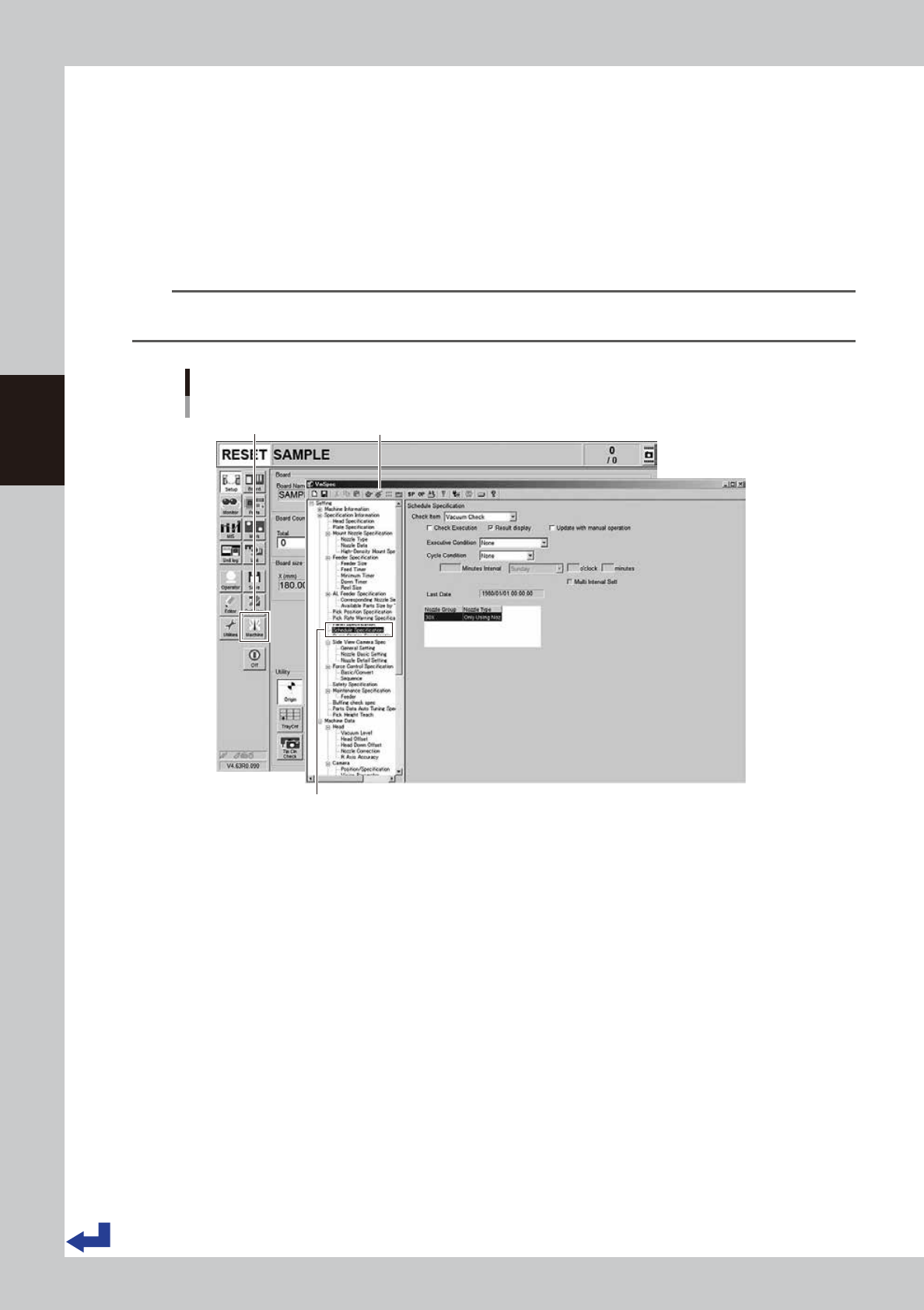
Press the [Machine] button.
The “VmSpec” screen appears.
2
Select the “Schedule Specification”.
Select the “Schedule Specification” on the left side of the "VmSpec" screen.
n
NOTE
The “Nozzle Tip Cleanliness Check” is a machine setting items. Accessing such parameters requires the administrator
level of authority.
Calling up “VmSpec” – “Schedule Specification” screen
[Machine] button “VmSpec” screen
Select “Schedule Specification”.
24318-KMK-00
3-27
3
Flow from starting up machine to production
3
Set the “Nozzle Tip Cleanliness Check”.
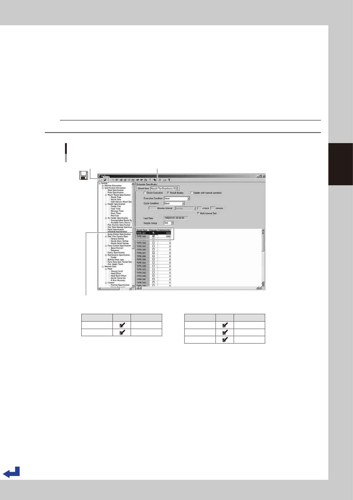
1. Pull down the “Check Item” and select “Nozzle Tip Cleanliness Check”.
2. Provide the check boxes of the object nozzles (standard specification: 301A/302A and narrowly
spaced nozzle specification: 311A, 312A/313A) with a check mark. Then, enter “1000” into the
“Database No.”
3. Press the “Save” icon on the upper left corner of the screen to save the settings.
4. Press the “Close [x]” icon on the upper right corner of the screen to exit the “VmSpec” screen.
4
Read out the board data again.
Reading out the board data again makes the Nozzle tip cleanliness check settings taken in.
TIP
The components database number “1000” is a recognition data dedicated to the nozzle tip cleanliness check.
Setting Nozzle Tip Cleanliness Check
[VmSpec] screen
1. Select check item “Nozzle Tip Cleanliness Check”.3. Press the “Save” icon.
2. Provide the check boxes “Execute” of the object nozzles with a check mark. Enter “1000” into the “Database No.”
Nozzle Type
TYPE-301
TYPE-302
Execute Database No.
1000
1000
■ Nozzle group 30X (Standard) ■ Nozzle group 31X (narrowly spaced type)
Nozzle Type
TYPE-311
TYPE-312
TYPE-313
Execute Database No.
1000
1000
1000
24319-KMK-00
3-28
3
Flow from starting up machine to production
1.10 Starting production
This procedure description in this section assumes that the board data to be used for production has been read
out.
1
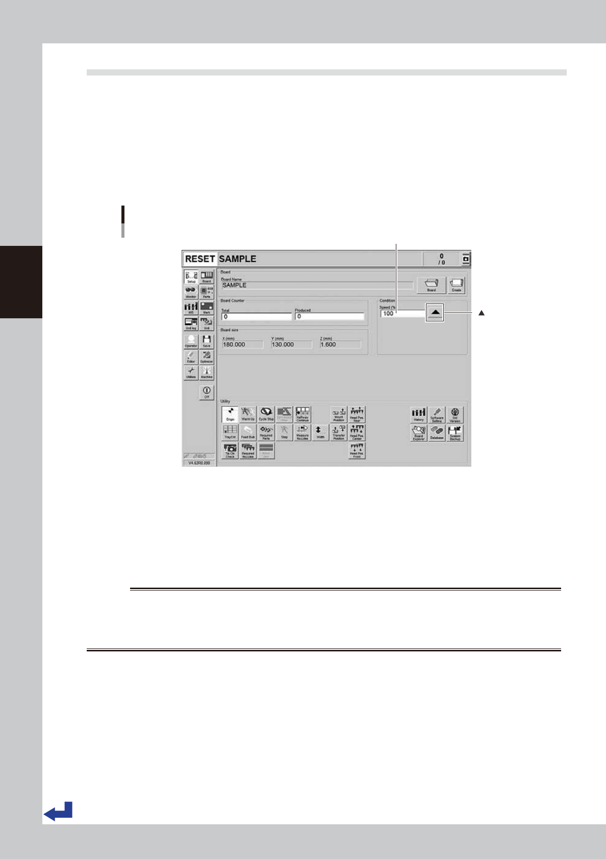
Set the operation speed.
Set the automatic operation speed. Although normally set to 100% of the speed, the operation speed
can be slowed down when it is necessary to confirm the operation such as testing the mounting of
components on a new board.
Change the operation speed by pressing the [
▲
] button of the “Condition” column on the “Setup”
screen or directly entering the speed values into the “Speed”.
Setting the operation speed
[Setup] screen
Set the operation speed.
[ ] button
24320-KMK-00
2
Start the automatic operation.
1. (If the emergency stop button has been pressed) Cancel the emergency stop and press the [READY]
button on the operation panel.
2. Press the [START] button on the operation panel. When the sensor at the loading port of the conveyor
detects a board, the conveyor belt starts rotating, transfers the board to the mounting position and
starts mounting the components on the board.
w
WARNING
THE GREEN SIGNAL LIGHT LIGHTS UP WHEN THE MACHINE IS OPERATING. THE SIGNAL LIGHT LIGHTS UP IN YELLOW (BLUE) IF
AN ERROR OCCURS OR MACHINE GOES THROUGH THE INTERLOCKED OPERATION. THE SIGNAL LIGHT LIGHTS UP IN RED
(WHITE) IN AN EMERGENCY STOP. MAKE ABSOLUTELY SURE THAT WHEN THE SIGNAL LIGHT STAYS GREEN, NEVER ATTEMPT
TO ENTER THE MOTION ENVELOPE OF THE HEAD UNITS.