YSM20R_YSM20WR_Ope_E.pdf - 第145页
2-42 2 Basic operation 4. Preparing component tape 4.1 T ape feeders 4.1.1 Setting component tape T aking up ZS feeder as an example, this section describes how to set component tape on the feeder . See “SS F eeder User’…
2-41
2
Basic operation
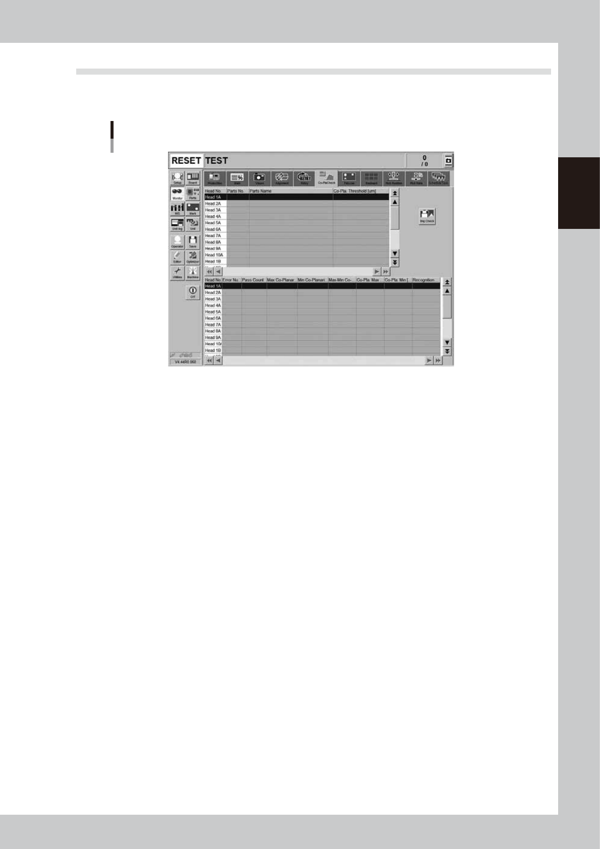
3.13 Coplanarity checker
This screen is displayed when the machine is equipped with a coplanarity checker (option). This screen shows
the results at real-time when using the coplanarity check or component recognition surface height check.
Monitor: Co-PlaCheck (Coplanarity Check)
24234-KMK-00
• Head No.
Displays the head number currently being used.
• Parts No.
Displays the part number currently being used.
• Parts Name
Displays the part name currently being used.
• Co-pla. Threshold [μm]
Displays the coplanarity tolerance that was set in parts information.
• Error Number
Displays coplanarity error numbers.
• Pass Count
Displays the number of images that were captured during coplanarity check.
• Max. Co-planarity Pos.
Displays the lead number that was measured as the maximum coplanarity value.
• Min. Co-planarity Pos.
Displays the lead number that was measured as the minimum coplanarity value.
• Max-Min Co-planarity [μm]
Displays the coplanarity measurement result.
• Co-planarity Max. [μm]
Displays the maximum coplanarity value.
• Co-planarity Min. [μm]
Displays the minimum coplanarity value.
• Recognition Height
Displays the recognition height (height to underside of components).
2-42
2
Basic operation
4. Preparing component tape
4.1 Tape feeders
4.1.1 Setting component tape
Taking up ZS feeder as an example, this section describes how to set component tape on the feeder.
See “SS Feeder User’s Manual” for the details and handling of SS feeder.
c
CAUTION
Always use a temporary tape set station or a power station for the off-line setup to set the tape. The tape cannot be
set directly on the mounter.
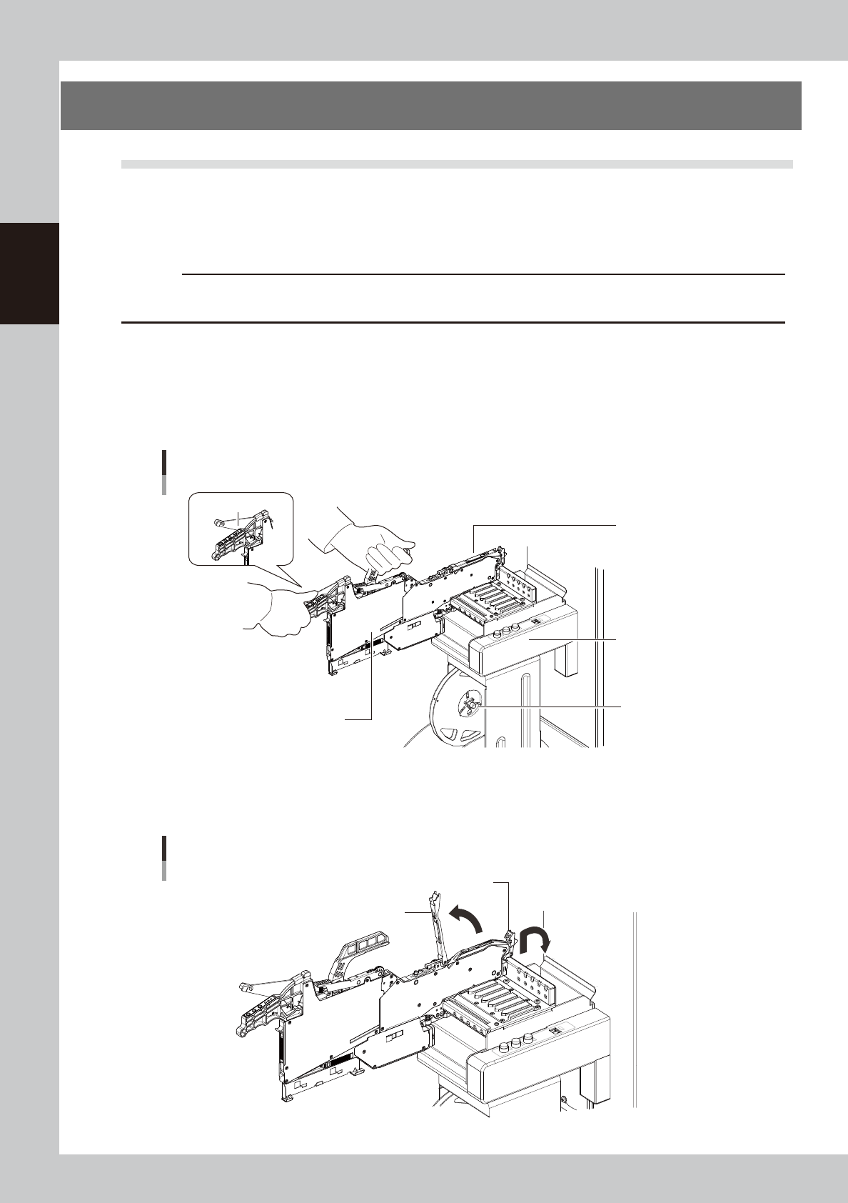
1
Set the feeder and tape reel.
1. Place the feeder in the temporary tape set station or power station for the off-line setup.
While keeping holding the unclamping lever of the feeder, slide to the extreme left set position (the
point where the feeder connector is present) and set it in place.
2. Set the tape reel for operation to the dedicated reel holder of the set-up station on machine.
Set in the extreme
left position.
Setting the feeder
Feeder
Unclamp lever
Temporary tape set
station
Reel holder
(7-inch reel)
23202-KMK-00
2
Raise the tape guide assembly.
Lower the front lever for the tape guide while lifting it, and raise the tape guide assembly.
Raising the tape guide assembly
Tape guide assembly
Tape guide front lever
23203-KMK-00
2-43
2
Basic operation
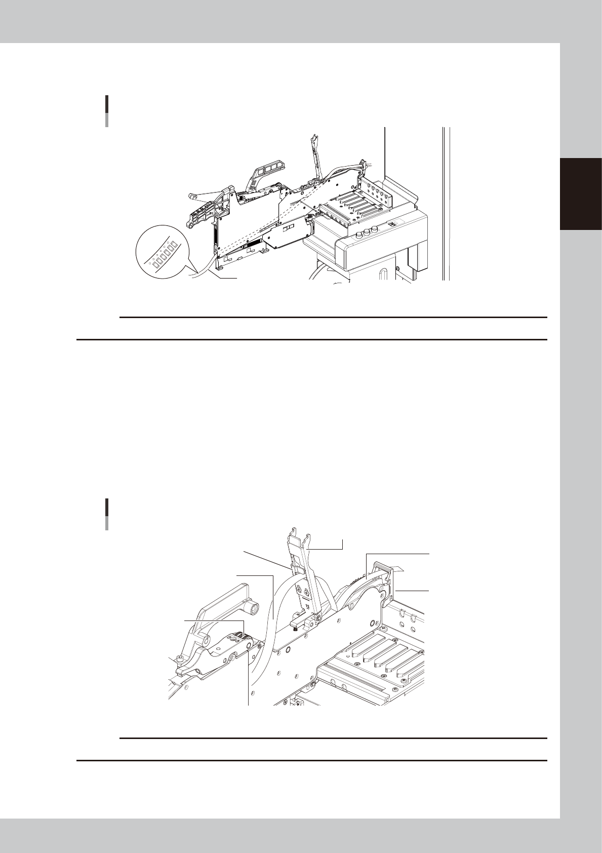
3
Set the tape in the tape feeder.
Put the tape in through the hole in the rear part of the feeder.
Tape
Be sure of the tape
top surface and back.
Mounting the tape
23204-KMK-00
c
CAUTION
Be sure to place the tape to the correct top/back orientation.
4
Peel off the cover tape.
The tape is in two layers – one called “carrier tape” that contains the components and the other called
“cover tape” that covers the components on the top. Remove the leading portion of the cover tape in
advance to the extent that the tape reaches the winding roller.
5
Set the carrier tape.
Run the carrier tape through the hole in the tape guide front lever.
6
Set the cover tape.
Run the cover tape through the notch in the tape guide assembly. Be sure to pull out enough tape so
the cover tape reaches the take-up roller.
Top guide front lever
Carrier tape and cover tape
Top guide assembly
Cover tape
Take-up roller
Carrier tape
Tape support plate
23205-KMK-00
c
CAUTION
When setting the tape through the unit, do not damage the tape guide assembly or the tape support plate.