YSM20R_YSM20WR_Ope_E.pdf - 第149页
2-46 2 Basic operation 0 Align the first component with the standb y position. If pressing the [FEED] button and the [BACK] button on the feeder , the tape can be transferred or returned with the pitch setting correspond…
2-45
2
Basic operation
8
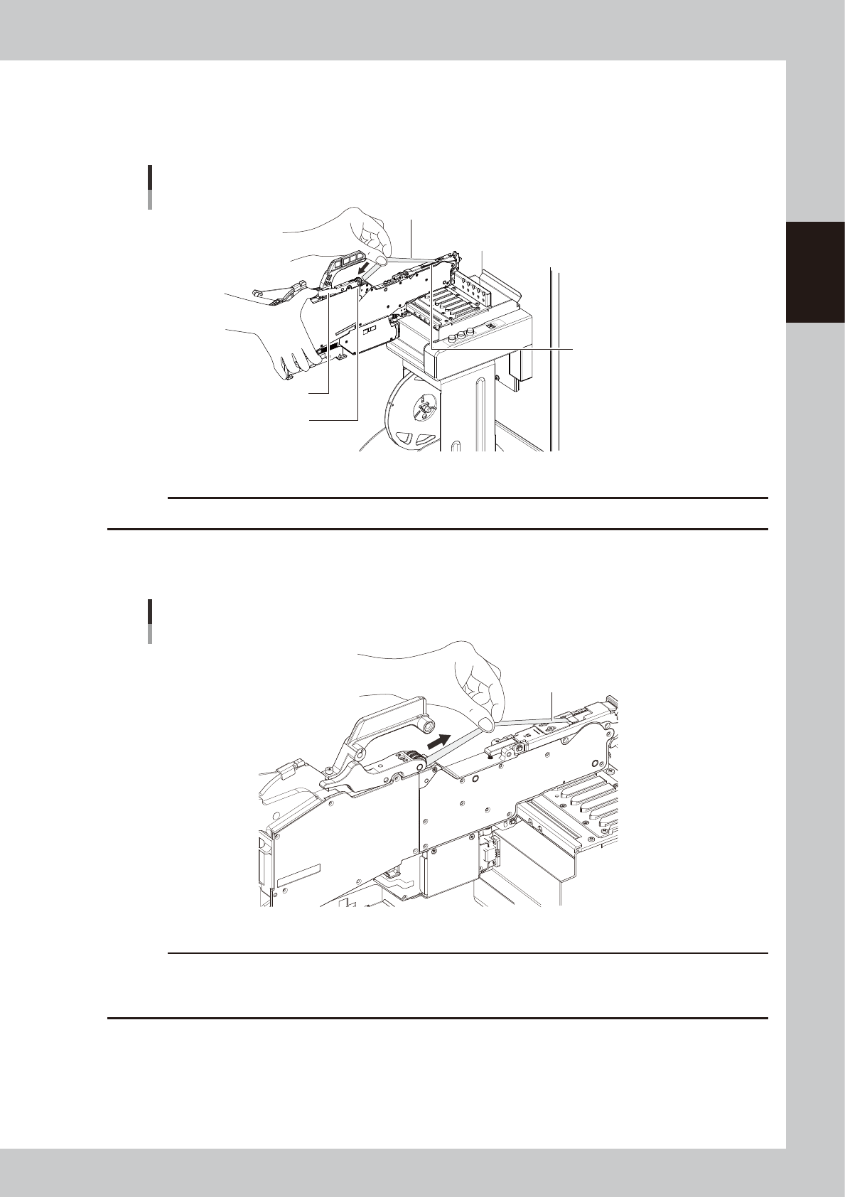
Set the cover tape in the take-up roller.
Push the portion of the P/O lever assembly shown in the figure to make a clearance. Insert a certain
amount of the cover tape into this clearance and release the winding roller lever to pinch the cover
tape.
Take-up roller
Setting the cover tape
Cover tape
P/O lever ASSY
Tape guide assembly
23208-KMK-00
c
CAUTION
Check that the cover tape has not become twisted between the take-up roller and the tape guide assembly.
9
Reel the cover tape to take up the slack.
Pull the cover tape lightly in the direction of the arrow and the slack will be taken up automatically.
Taking up the slack of the cover tape
Cover tape
23209-KMK-00
c
CAUTION
• Using your hand, make sure the cover tape winds up straight.
• Reel the cover tape until the device takes up all slacks on the tap tape.
• During this task be careful not to cut your fingers while winding the cover tape.
2-46
2
Basic operation
0
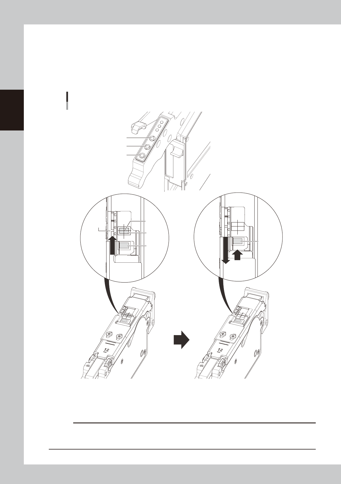
Align the first component with the standby position.
If pressing the [FEED] button and the [BACK] button on the feeder, the tape can be transferred or
returned with the pitch setting corresponding to the feeder type.
1. Press the [FEED] button and transfer the tape to locate the first component on the temporary pickup
position (marking (white)).
2. After pressing the component pitch and the [BACK] button once to return the component, press the
[FEED] button once and align the first component with the standby position.
Operation buttons and adjusting component position
[FUNC] button
[BACK] button
[FEED] button
Press the [FEED] button to feed the
component to the pickup position.
Press the component pitch and the [BACK] button
once to return the component. Then press the [FEED]
button once and align the first component with the
standby position.
Pickup
position
Marking
First
component
Standby
position
First
component
(Standby
position)
23210-KMK-00
c
CAUTION
Make sure to align the standby position by the [FEED] button. Press the [BACK] button more than twice to return the
component. Then press the [FEED] button to align the component with the standby position. If aligning the standby
position by the [BACK] button, the pickup position offset of the fist component will occur.
2-47
2
Basic operation
n
Button operations and corresponding feed pitches
Feeder type Setting Pitch
[FEED], [BACK]
Pressed 1 Time
[FUNK+FEED]
[FUNC+BACK]
Pressed 1 Time
ZSY-004 All pitches 1 mm 1 mm
ZSY-008
0 2 mm
1 mm1 1 mm
2 and higher 2 mm
ZSY - 2T6, 024,
032, 044, 056,
072, 088, 104
0
2 mm
2 mm
2 and higher Setting pitch
TIP
• For handling the feeder of 12 mm or wider, set the components pitch on the temporary tape set station / the
power station. Then, press the “FUNC” and “FEED” buttons or the “FUNC” and “BACK” buttons simultaneously. The
feeder feeds the tape by the set pitch. See the methods of memorizing feeder feed pitch in each station in
"4.1.4 Setting board data of component tape" in this chapter for the setting, .
• Continuous feed is possible by pressing and holding the "FEED / BACK" button.
• There is no continuous feed for the "FUNC + FEED" and "FUNC + BACK" buttons (even if pressed and held).
• See the “SS Feeder User’s Manual” for setting the feed rate of SS feeder.
q
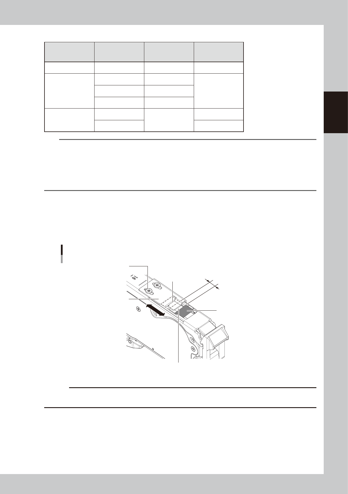
Check the tape support plate position.
If the feeder type is 12 mm or wider, it is required to adjust the tape support plate according to the
components shape. Adjust the tape support plate position by loosening the 2 adjustment screws.
Locate the leading edge of the tape support plate between the standby position and the pickup
position (closer to the pickup position). Locate the leading edge of the tape support plate somewhat
closer to the pickup position between the standby position and the pickup position.
The leading edge of tape support plate
Aligning position of the tape support plate
Pickup position
Tape support plate
Adjustment screw
Standby position
Slide the tape support plate
to adjust the position.
Locate the leading edge of the tape
support plate somewhat closer to the
pickup position in the section.
23211-KMK-00
c
CAUTION
If the tape support plate is not adjusted, the components positions after removing the cover tape may get unstable,
causing possible incorrect components pickup.