YSM20R_YSM20WR_Ope_E.pdf - 第209页
3-21 3 Flow fr om starting up machine to production 1.7 Preparing component tape (T ape feeder) When the convey or gets ready for operation, prepare the component tape. This procedure description in this section assumes …

3-20
3
Flow from starting up machine to production
3
(YSM20R Dual-stage type) Check the board clamped on the downstream stage.
1. (Carriage type machine) Attach the carriage.
2. Close the safety cover and release the [EMERGENCY STOP] button.
3. Press the [Convey Board] on [Unit] - [Conveyor] screen.
4. The "Convey Board" check screen appears. Confirm that "All position" is ticked, and then press the [OK]
button.
5. The "CONVEY AND FIX" screen appears. The board is transferred from the upstream stage to the
downstream stage, and the board is fixed on the mount position of the downstream stage.
6. See step 2 to check the conveyor fixed condition on the downstream stage.
4
Remove the board.
1. If the carriage type machine, attach the carriage.
2. Close the safety cover and release the [EMERGENCY STOP] button.
3. (YSM20R Dual-stage type) Press the [Convey Board] button on [Unit] - [Conveyor] screen.
(YSM20R Single-lane / YSM20WR Dual-lane type) Press the [Convey Out] button on [Unit] - [Conveyor]
screen.
4. (YSM20R Dual-stage type) The "Convey Board" check screen appears. Confirm that "All position" is
ticked, and then press the [OK] button.
5. The "CONVEY AND FIX" screen appear. The board is transferred from the mounting position (YSM20R
Dual-stage type: downstream stage) to the exit.
6. Remove the board manually.
3-21
3
Flow from starting up machine to production
1.7 Preparing component tape (Tape feeder)
When the conveyor gets ready for operation, prepare the component tape. This procedure description in this
section assumes that the board data to be used for production has been read out.
1
Call up the “Required Parts” screen.
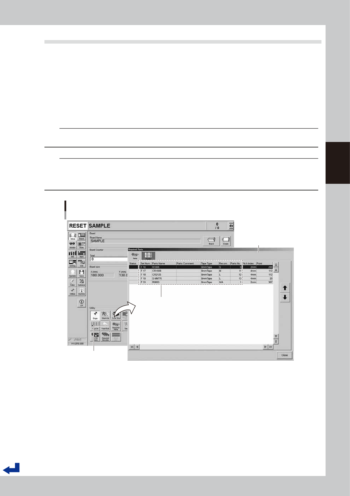
Pressing the [Required Parts] button makes the “Required Parts” screen pop up.
2
Set the feeders loaded with component tape.
The “Required Parts” screen lists the “Set Num.”, “Parts Name”, “Parts No.” and other parameters. While
observing this list, attach the feeders loaded with component tape in each corresponding feeder set
location.
n
NOTE
See chapter 2,"4. Preparing component tape" for the procedure to set component tape into the feeder and attach
the feeder on the main machine.
n
NOTE
The component set positions (Set Num.) F1 through F64 are in the front feeder bank and the F101 through F164 are in
the rear feeder bank.
P1 to P30 are the pallet numbers for the tray component supply unit at front side, P101 to P130 are the pallet numbers
for the tray component supply unit at rear side.
Set Num. : F1 to F64 are set in the front feeder bank
F101 to F164 are set in the rear feeder bank
P1 to P30 are set in the front tray component supply unit
P101 to P130 are set in the rear tray component supply unit
Set Num. / Parts Name / Tape Type / Parts No. and other parameters appear.
Preparing component tape
[Setup] screen - “Required Parts” screen
“Required Parts” screen
[Required Parts] button
24313-KMK-00
3-22
3
Flow from starting up machine to production
1.8 Preparing tray component supply unit
Prepare the tray components. This procedure description in this section assumes that the board data to be used
for production has been read out.
1
Call up the “Required Parts” screen.
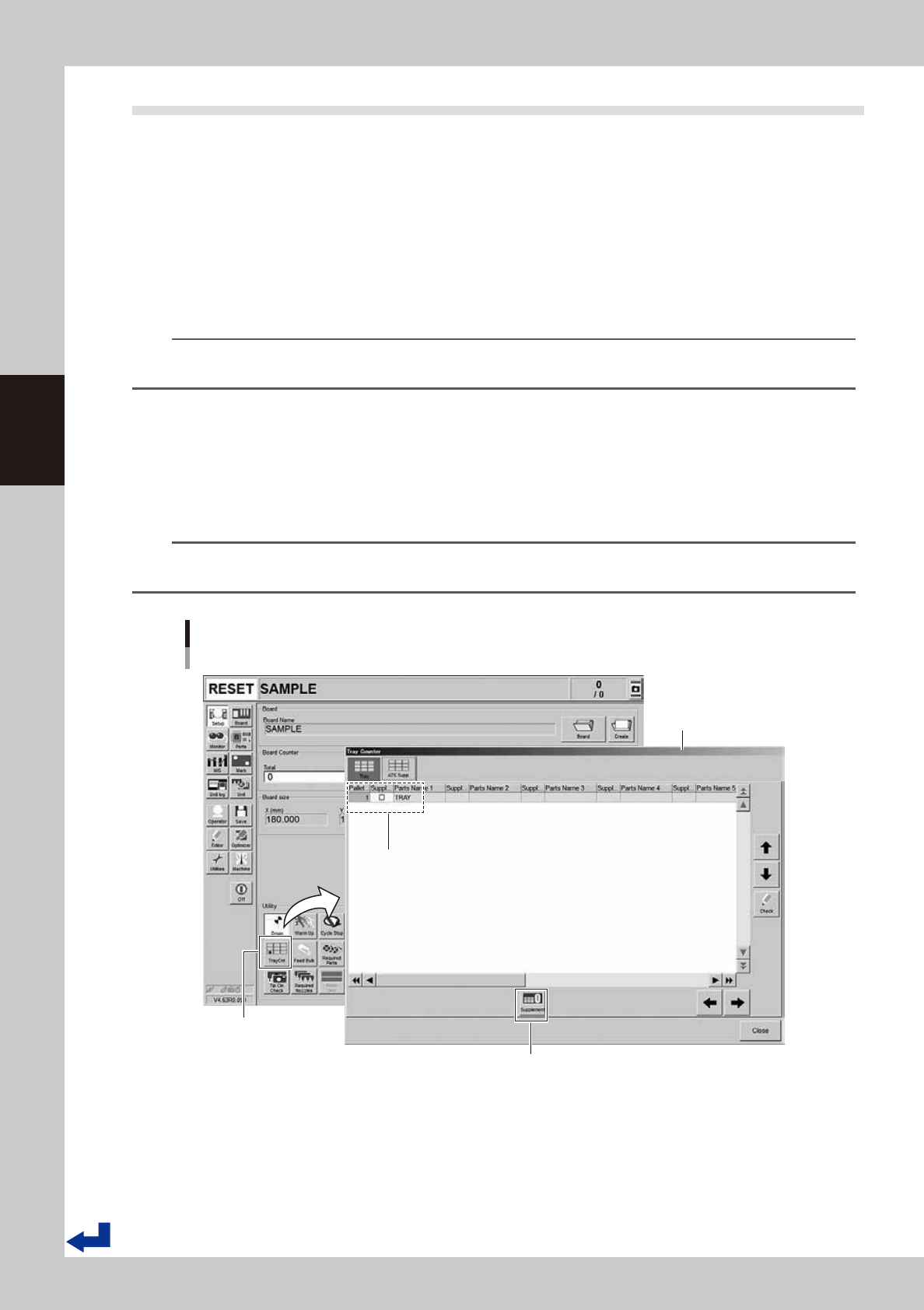
Pressing the [Required Parts] button makes the “Required Parts” screen pop up.
2
Set the pallets loaded with components.
There are several information such as "Set Num.", "Parts Name" and "Parts No." listed in [Required Parts]
screen. "Set Num." for the tray components are indicated with "P1 to P30 and P101 to P130". Set the
pallets loaded with components onto the rack where the tray component supply unit is to be set.
n
NOTE
See Chapter 2, "5. Preparing tray component supply unit" for the procedure to set the magazine and the pallet on
the tray component supply unit.
n
“Tray Counter” – “ATS Supp.” screen
If the machine is equipped with the tray component supply unit, pressing the [TrayCnt] button on the “Setup” screen calls
up the “Tray Counter” screen. The “ATS Supp.” tab of the “Tray Counter” screen allows the same operation as that of the
pallet indicator button on the screen. After setting a pallet, provide “Supplement Check” with a check mark. Then, press
the [Supplement] button. This completes the replenishing the pallet components.
TIP
When completing replenishing the pallet components, the “Supplement Check” column changes the color from
yellow to blue.
Setting tray components
“Tray Counter” - ”ATS Supp.” screen
[TrayCnt] button
“Tray Counter” - ”ATS Supp.”
screen
[Supplement] button
After setting a pallet, provide “Supplement Check” of the set pallet number
with a check mark. Then, press the [Supplement] button.
24314-KMK-00