YSM20R_YSM20WR_Ope_E.pdf - 第196页
3-8 3 Flow fr om starting up machine to production 1.6 Conveyor unit setup Set up (Get ready) the con vey or unit according to the selected board data. T he following 3 tasks for setting up the convey or unit are require…
3-7
3
Flow from starting up machine to production
1.5 Selecting the board data
Select the board data used for production from those registered.
1
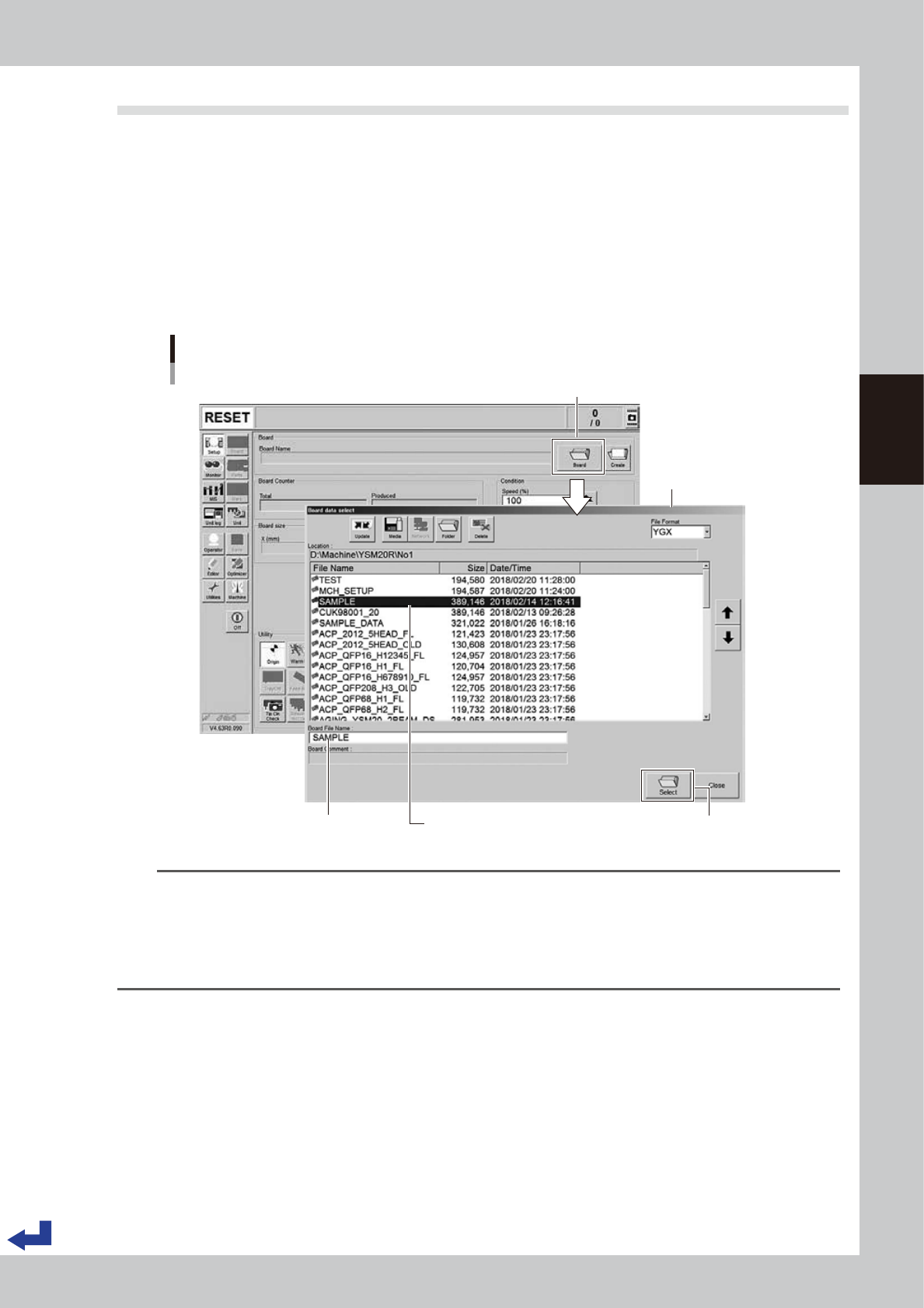
Call up the “Board Data Select” screen.
Press the [Board] button on the “Setup” screen to call up the “Board Data Select” screen.
YSM20WR Dual-lane: Press the [Lane switch] button to select the lane to be used for production.
(When using both lanes for production, press the [Lane Combine] button.)
2
Select the board data.
Select the board data used for the production from the list on the “Board Data Select” screen. Press the
[Select] button. The machine reads out the selected board data.
“Board data select” screen
[Select] button
Selecting the board data
[Setup] screen
Selected board name is displayed. Selected board name is displayed.
Press [Board] button.
24306-KMK-00
TIP
When using YSM20WR Dual-lane:
• Pressing the [Lane Combine] button displays the combined board data.
The combined board data is a board file that combined 2 board data. The combined board data is displayed in
orange.
• When selecting the combined board data, the board file name and board data name to be produced on the
selected lane are displayed on the free area of the "Setup" screen.
3-8
3
Flow from starting up machine to production
1.6 Conveyor unit setup
Set up (Get ready) the conveyor unit according to the selected board data.
The following 3 tasks for setting up the conveyor unit are required– “Push-up pin layout”, “Adjusting board
hold plate position” and “Checking state of clamping board”.
n
NOTE
When producing with the both lanes of dual-lane, press the [Lane switch] button to set up the lane to be operated.
n
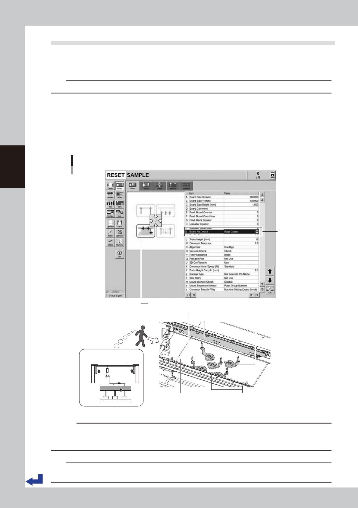
Board clamping method
Normally, the machine follows the “Edge clamp” method to clamp a board. The procedure is as follows.
1. The board transferred on conveyor stops at the mounting position when it comes into contact with the main stopper.
2. The clamp board assembly pushes up the edge of the board so that the board is secured in place between the clamp
board assembly and the board hold plate.
3. Other than the edge of the board, the push-up pins support the board from under.
Figure of board clamped (side view)
C. Push-up pins
A. Push-up plate
B. Clamp board assembly
Main stopper
Board
D. Board hold plat
BB
DD
C
A
Board clamping
method
Figure of board clamped
Board clamping method
24329-KMK-00
c
CAUTION
If the board to be processed has a slit or the like, some of the conveyor sensors might not be able to detect the board.
In such a case, changing the machine settings and adjusting the sensor positions might be required. Before starting
the actual production, make absolutely sure that the boards are transferred correctly as intended.
n
NOTE
This machine follows the “Edge clamp” method to clamp a board. If using other method to clamp the board, the
machine may need to be modified or evaluated.
3-9
3
Flow from starting up machine to production
1.6.1 Laying out push-up pins
c
CAUTION
The procedure described in this section requires the conveyor unit and push-up plate to actually operate to get ready
for production. Before starting the procedure in this section, be absolutely sure to check the conveyor and its
peripherals according to "1.1 Pre-operation check" in this chapter.
1
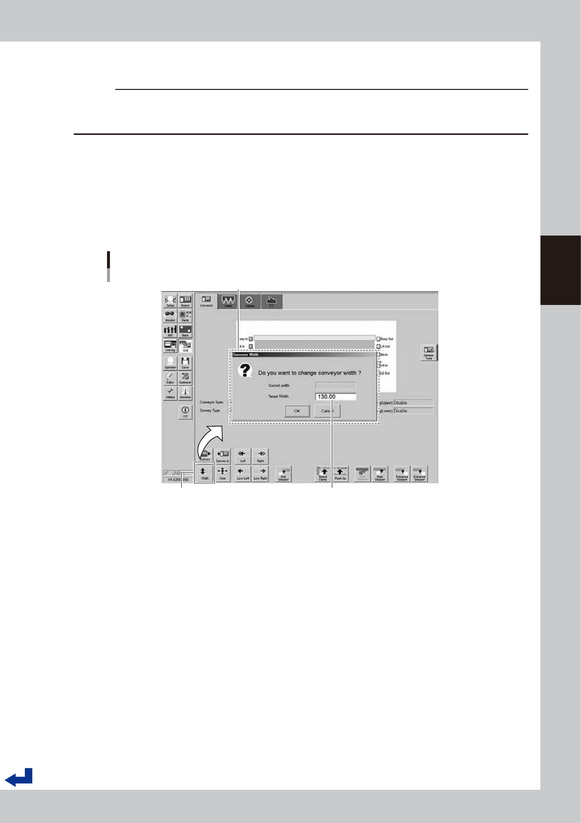
Change the conveyor width.
n
YSM20R Single-lane / YSM20WR Dual-lane
1. Press the [Width] button on the “Unit” – “Conveyor” screen.
2. The conveyor width designated by the board data appears on the “Conveyor Width” screen as the
“Target Width”. Confirm the conveyor width is correct and Press the [OK] button. The conveyor unit
adjusts itself to the designated conveyor width.
Changing conveyor width
[Unit] - [Conveyor] screen
“Conveyor Width” screen
The conveyor width designated by the board data appears here.
[Width] (conveyor) button
24307-KMK-00