YSM20R_YSM20WR_Ope_E.pdf - 第128页
2-25 2 Basic operation • W orking Ratio T his is the machine's independent working ratio that is not affected by the status of the upstream and do wnstream machines. The following expression calculates the w orking …
2-24
2
Basic operation
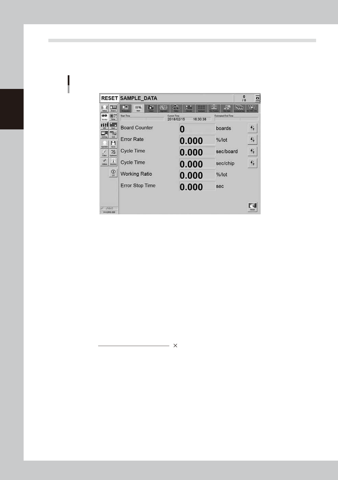
3.2 Main
The [Monitor] - [Main] tab screen shows you the real-time production status such as the board count and cycle
time. Displaying this screen during production is handy. All information will be cleared when the board type is
changed.
Monitor: Main
24213-KMK-00
• Start Time
Displays the date and time that the board data currently being produced was changed.
• Estimated End Time
Displays the estimated time of finishing the production.
• Current Time
Displays the current date and time of the system clock time built-in the machine.
• Board Counter
The board counter displays the number of boards produced after changing to the current production board data. The
board counter counts only the boards completed the mounting. Pressing the button on the right side allows to switch
between “Board Counter” and “Block Counter”.
• Error Rate
The ratio of components discarded due to the pick up error or recognition error occurred from the time of changing to
the board data currently producing to present to all the consumed components. This data is updated when changing the
production board.
Number of discarded components
Total component consumption
Error rate (%) = 100
Pressing the button on the right allows to switch between “Error Rate” and “Pickup Rate (= 100% - Error Rate)”.
• Cycle Time (sec/board)
The cycle time shows the average (seconds/board) of the mounting time per board. The data is updated when the
mounting is completed.
Pressing the button on the right allows to switch among “Cycle time”, “Mount CT (cycle time)” and “Transfer CT (cycle
time)”. The Cycle Time = Mount CT + Transfer CT.
The Mount CT (cycle time) includes the board mark recognition time such as fiducial bad marks, component recognition
time, mounting time, retry operation time, component discarding time and nozzle changing times. The stopping time due
to an error and the [Stop] button is not included.
• Cycle Time (sec/chip)
Shows the time (seconds) to mount one component on the board. This is the time obtained by dividing the time for one
sequence from pickup to mounting by the number of components mounted in that sequence.
Pressing the button on the right switches the indications among “Cycle time (sec/chip)”, “Cycle time (sec/block)”, “Cycle
time (chip/hour)”, “Cycle time (block/hour)” and “Cycle time (board/hour)”.

2-25
2
Basic operation
• Working Ratio
This is the machine's independent working ratio that is not affected by the status of the upstream and downstream
machines. The following expression calculates the working ratio.
Cumulative mounting time + cumulative transfer time
(Production completion time - setup completion time) - cumulative standby time
×
100
Working ratio (%)
=
• Cumulative mounting time : Total time that head unit is operating
• Cumulative transfer time : Total transfer time (board loading/unloading)
• Cumulative standby time : Total standby time due to upstream or downstream machine
• Production completion time : Time changed to next production board
• Setup completion time : Time [START] button was pressed and operation started
• Error Stop Time
Shows the machine stop time by error. This is a period of time until the [CLEAR] button is pressed from the error
occurrence.
• [Reset] button
This resets the production control information of the production data. It resets each piece of data displayed on the screen,
current production quantity and scheduled production quantity. The "Board Counter" value on the Setup screen is also
reset when this production data is reset.
2-26
2
Basic operation
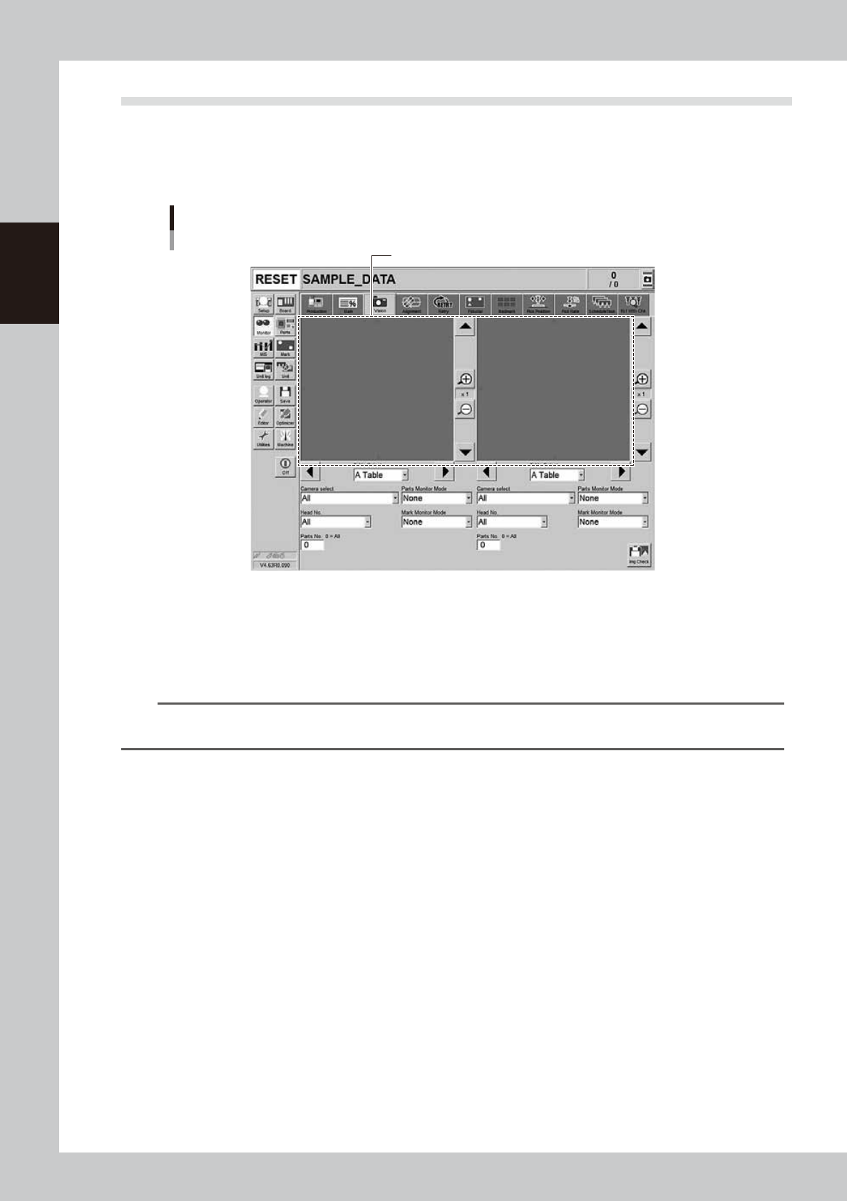
3.3 Vision
The recognized image area on the screen shows the image when the machine recognizes a board mark, bad
mark or component during the automatic operation. However, the area shows only the image of the lastly
recognized component when the high speed, continuous component recognition are performed such as by the
multi camera.
Recognition image display
Monitor: Vision
24214-KMK-00
• Table select/ Camera select / Head No.
A desired head unit, a camera number and a head number can be selected.
• Parts number
Inputting a desired part number makes the list display only its part image. Inputting "0" shows all the part images.
n
NOTE
An image is displayed on each left and right of the vision monitor. Select a table, a camera, a head and a part
number for each monitor so that the images can be compared with each other.
• Enlarge/reduce buttons
The recognition result image can be enlarged from 1 to 16 times by pressing the enlarge (+) button. The image can be
reduced to 1/16 by pressing the reduce (-) button. Note that when the image is enlarged, the smooth component edges
may appear jagged, and when reduced, gray sections may appear around the edges. But this is not a fault.
• Up/down/left/right buttons
The arrow buttons on the upper right and lower right corners of the image screen move the image vertically. The arrow
buttons on the lower left and lower right of the image screen move the image left to right or right to left. Use these arrow
buttons to view a section of the image that is not displayed on the screen.
• Parts Monitor Mode
This specifies the mode for displaying the components on the monitor during vision recognition. Depending on the
selected item, the recognition results and detection range window will appear on the image. This monitor mode can also
be changed during operation.
"None"
Displays the image taken by the camera. The recognition result values are not displayed.
"Vision Result"
Displays information such as the recognition results X, Y and R direction position (pixels) and number of detection
leads. Note that the displayed items will differ according to the component recognition type.
"Detection Range"
Draws a window for the component detection range. If the component does not fit within the detection range, it will
not be recognized correctly. In this case, check the pickup state or correct the component data.