YSM20R_YSM20WR_Ope_E.pdf - 第136页
2-33 2 Basic operation • T ape T ype T he T ape T ype shows the type of tape when the mac hine processes component tapes. It shows the method of supplying components when processing tra y components. • X (mm), Y (mm) Dis…
2-32
2
Basic operation
3.8 Pick Pos. (Pickup position offset)
n
NOTE
Pickup position offset function applies to the components satisfying the following conditions.
• The correct Mode on [Machine] - [Specification Information] - [Pick Position Specification] is set to either "Use"
or "Use with Feeder Correction".
• Component picked up with a nozzle that the "Available" on [Machine] - [Specification Information] - [Pick Position
Specification] is set to "Use".
• Component that "E: Pick Pos Correction" is set to "Use" on [Parts] - [Option] tab screen of the board data.
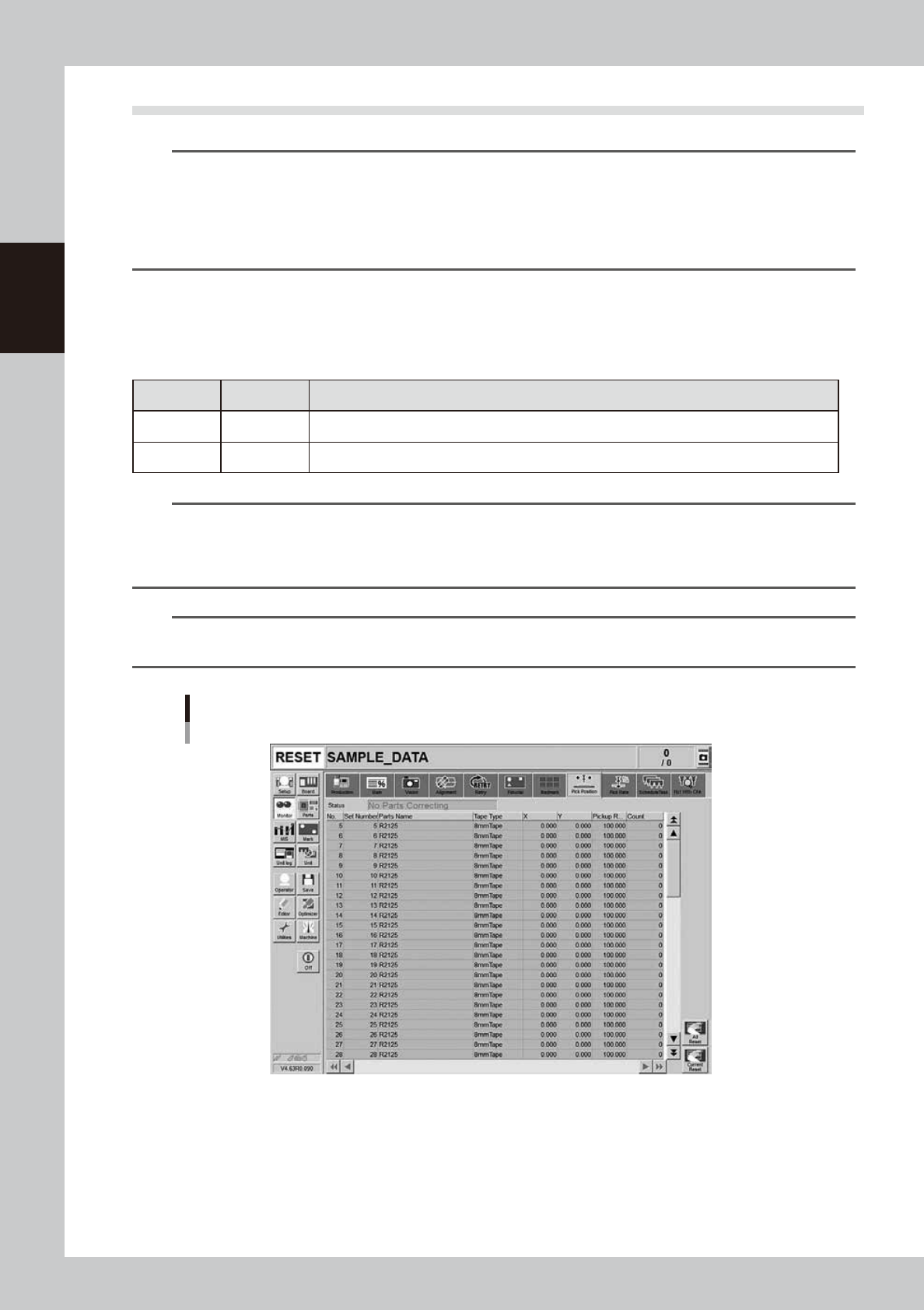
This screen appears when the pickup position offset function is used. This screen allows to check how the
pickup position of the object component (feeder) is corrected. If either the X or the Y correction amount
exceeds the warning zone or the error zone set up in the machine setting, the corresponding component in the
components list changes its color.
n
Display color
Color of row Status Description
Yellow Warning Exceeds warning level figure for each nozzle data set in pickup position offset specifications.
Red Error Exceeds error level figure for each nozzle data set in pickup position offset specifications.
n
NOTE
Warning generated: The machine generates an error message. The yellow lamp on the signal lamp tower flashes. The
machine, however, can continue the operation.
Experiencing error: The machine generates an error message when finishing producing one board. The machine
cannot continue the operation.
n
NOTE
The numerical values specified in the warning level and error level of the pickup position offset specification are
machine data setting items. Accessing such parameters require the administrator level of authority.
Monitor: Pick Pos. (Pickup position offset)
24219-KMK-00
• No.
Displays the component No. (Parts screen data No.).
• Set No.
Displays the feeder set No.
• Parts Name
Displays the component name.

2-33
2
Basic operation
• Tape Type
The Tape Type shows the type of tape when the machine processes component tapes. It shows the method of supplying
components when processing tray components.
• X (mm), Y (mm)
Displays the amount of pickup position offset. The figure shown is the amount of error from the nozzle center position
towards the X-direction and Y-direction.
• Pick Rate (%)
Displays the component pickup rate of the nozzle for which the pickup position offset function is on (enabled).
• Count
Displays the number of components that were picked and placed by the nozzle for which the pickup position offset
function is on (enabled).
• [All Reset] button
This button clears and resets pickup position offset data for all components shown on the monitor.
• [Current Reset] button
Clears and resets pickup position offset data for a component selected from among the components shown on the
monitor display.
2-34
2
Basic operation
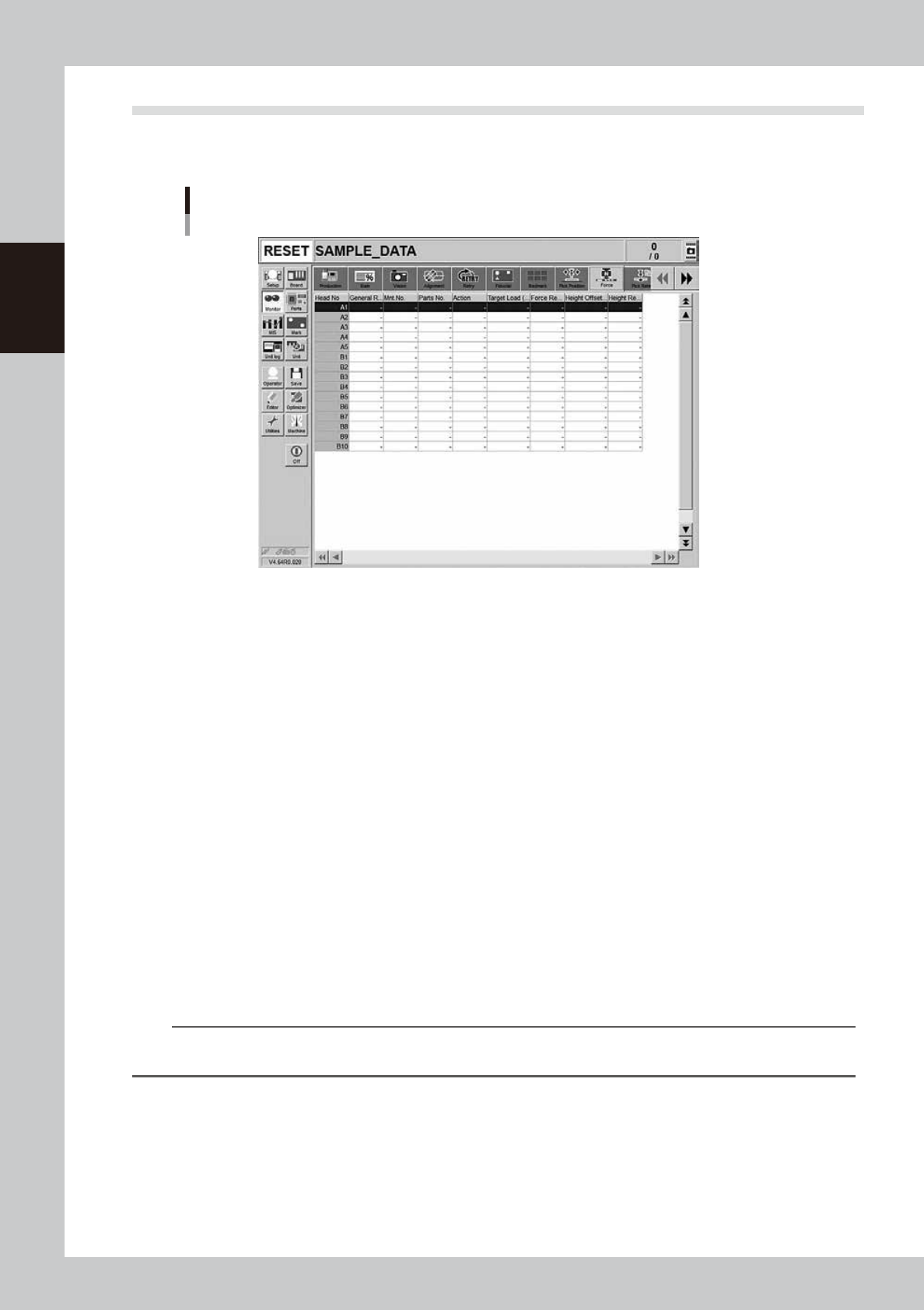
3.9 Force
This screen is displayed when the machine is equipped with a FM head. This screen shows the results at
real-time when using the force control.
Monitor: Force
24233-KMK-00
• Head No.
Displays the head number.
• General Result
Displays the general results of the force result and height result.
• Mnt. No.
Displays the mounting number.
• Parts No.
Displays the parts number.
• Action
Displays the force control execution action. (Pickup, dipping, mounting)
• Target Load (N)
Displays the target load (N).
• Force Result
Displays the force control result. The force control result shows NG if there is no board or component when executing
the force control.
• Height Offset (mm)
Displays the offset distance from the target coordinates. The upper portion shows the plus (+) direction.
• Height Result
Displays the result when the height offset (mm) result is compared with the error judgment distance.
n
NOTE
As the numeric value changes of the pickup, dipping, and mounting error judgment distances are the items in the
Machine Setting, the administrator level authority is needed.