YSM20R_YSM20WR_Ope_E.pdf - 第58页
1-25 1 Unit names and functions 4. Component supply section 4.1 Machine layout A feeder plate to install the tape feeder , etc., and a power connector or an air connector to dri ve the option devices are installed in the…
1-24
1
Unit names and functions
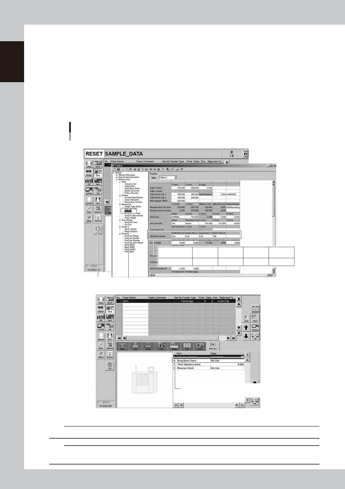
3.4.4 Shaft blow dump of very small components
Regarding to disposal of very small components less than 0603 size on this machine, if some components or
dust are recognized at checking after disposing operation, the air-blow station continues the shaft blow dump.
The target components for the shaft blow dump are determined by the following three settings.
1. The machine is equipped with the air-blow station.
2. The function of the shaft blow dump is set "Use" in "Machine Data"-"Mechanical"-"Position" and "Dump
Size" and "Blow Timer" are appropriately set.
3. The size of the component to be disposed of is less than the setting value in 2.
Additionally, to check the disposal, if "B: Bring Back Check" in [Parts]-[Side View] is set with "Use", the side
view camera is used for judgement. If it is set with "Not Use", the vacuum pressure check is used for
judgement.
Setting the Shaft Blow Dump
Board data : [Parts] - [Side View]
Setting : “Machine Data” - ”Mechanical” - “Position”
[Machine] button
“Mechanical” - ”Position”
Shaft Blow Dump
Dump Size
X (mm)
0.4
Dump Size
Y (mm)
0.8
Shaft Blow
Dump
Use
Blow Timer
(msec)
100
B Bring Back Check/Use : Judged by the side view camera
Bring Back Check/ Not Use : Judged by the vacuum pressure
24108-KMK-00
n
NOTE
The shaft blow dump doesn't work if "Shaft Blow Dump" is set with "Not Use", "Dump size" is "0" or "Blow timer" is "0".
TIP
The setting in the figure above is the recommended setting that the shaft blow is only applicable for small components
less than size 0603.
1-25
1
Unit names and functions
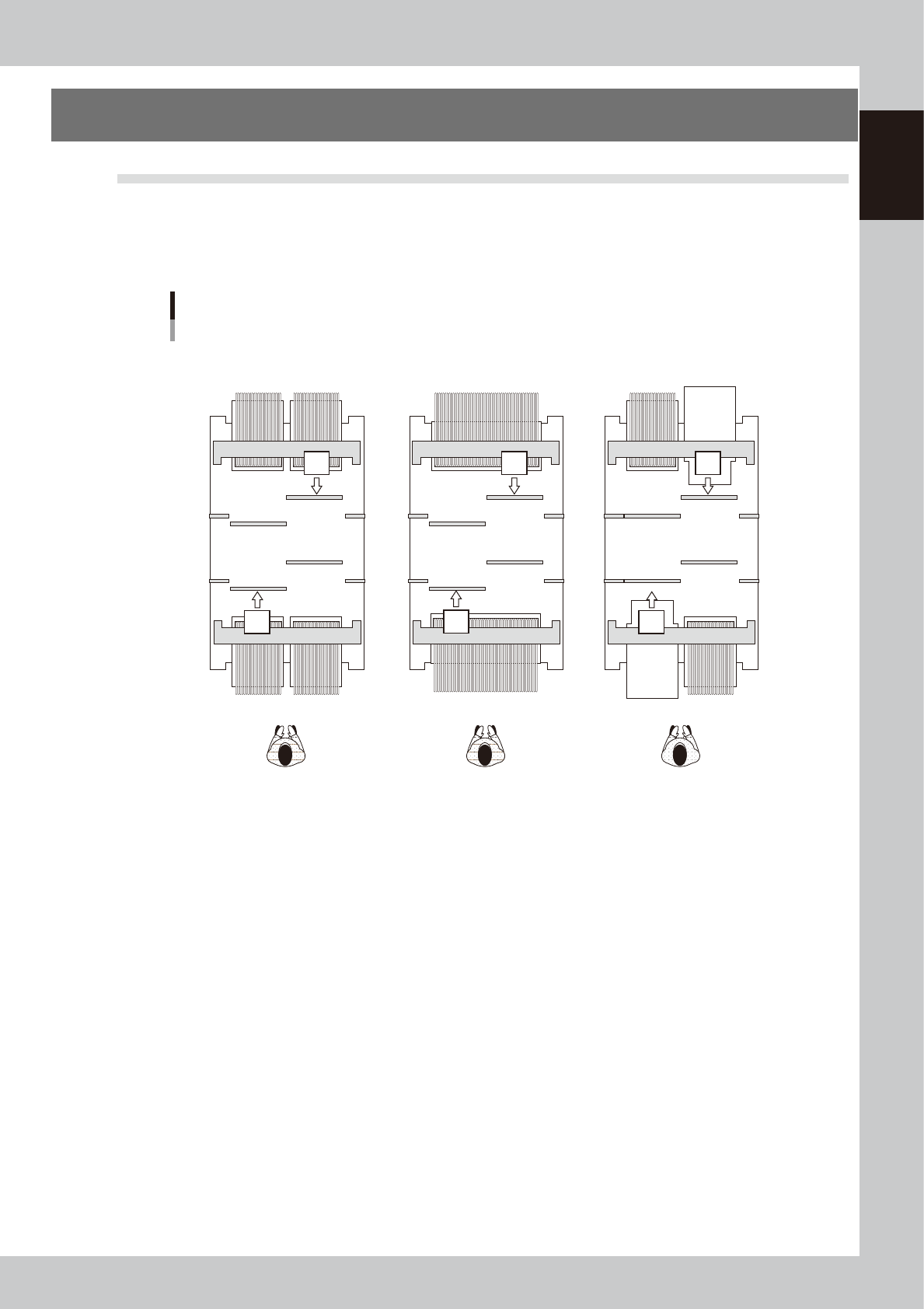
4. Component supply section
4.1 Machine layout
A feeder plate to install the tape feeder, etc., and a power connector or an air connector to drive the option
devices are installed in the feeder setting section.
n
Component supply formats
1 32 33 6464
164 132 101 164 133
1 70
170 101
cATS10 or
sATS30 or
sATS30NS
cATS10 or
sATS30 or
sATS30NS
Machine layout
Example of dual-stage, 2-beam
32-reel feeder exchange carriage x 4 units 70-reel fixed bank x 2 Front or rear ATS
23116-KMK-00
1-26
1
Unit names and functions
n
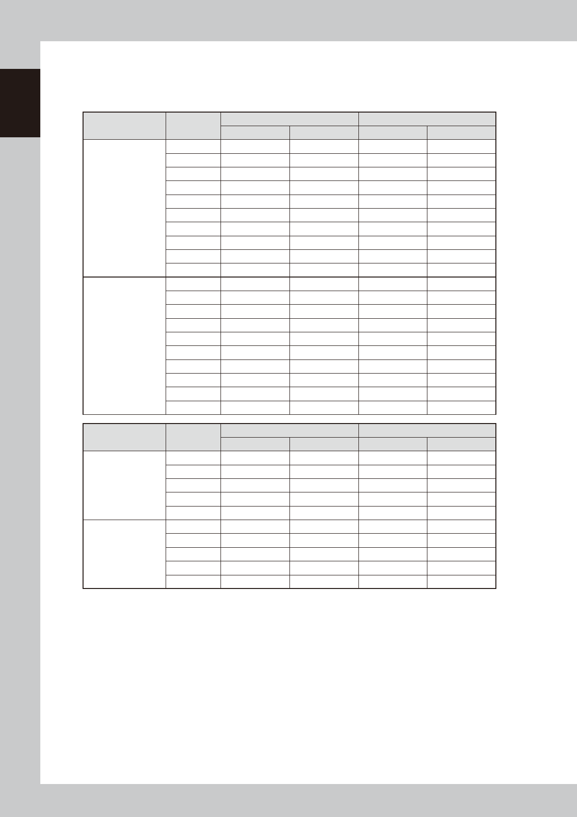
Head No. and feeder set No.
The feeder set number which can be used by each head depends on the head assembly configuration, X-axis movable
range and the table location.
The tables below show feeder set numbers that can be accessed by each head of the machine.
HM Head Head No.
Feeder exchange carriage (32-reel) Fixed (70-reel)
Front/A table Rear/B table Front/A table Rear/B table
1-beam
1 6 – 64 101 – 155 6 – 70 101 – 161
2 5 – 63 101 – 156 5 – 69 101 – 162
3 4 – 62 101 – 157 4 – 68 101 – 163
4 3 – 61 101 – 158 3 – 67 101 – 164
5 2 – 60 101 – 159 2 – 66 101 – 165
6 1 – 59 102 – 160 1 – 65 102 – 166
7 1 – 58 103 – 161 1 – 64 103 – 167
8 1 – 57 104 – 162 1 – 63 104 – 168
9 1 – 56 105 – 163 1 – 62 105 – 169
10 1 – 55 106 – 164 1 – 61 106 – 170
2-beam
1 1 – 55 101 – 155 1 – 61 101 – 161
2 1 – 56 101 – 156 1 – 62 101 – 162
3 1 – 57 101 – 157 1 – 63 101 – 163
4 1 – 58 101 – 158 1 – 64 101 – 164
5 1 – 59 101 – 159 1 – 65 101 – 165
6 2 – 60 102 – 160 2 – 66 102 – 166
7 3 – 61 103 – 161 3 – 67 103 – 167
8 4 – 62 104 – 162 4 – 68 104 – 168
9 5 – 63 105 – 163 5 – 69 105 – 169
10 6 – 64 106 – 164 6 – 70 106 – 170
FM Head Head No.
Feeder exchange carriage (32-reel) Fixed (70-reel)
Front/A table Rear/B table Front/A table Rear/B table
1-beam
1 6 – 63 101 – 155 6 – 63 101 – 161
2 4 – 61 101 – 157 4 – 61 101 – 163
3 2 – 59 102 – 159 2 – 59 102 – 165
4 1 – 57 104 – 161 1 – 57 104 – 167
5 1 – 55 106 – 163 1 – 55 106 – 169
2-beam
1 1 – 55 101 – 155 1 – 61 101 – 161
2 1 – 57 101 – 157 1 – 63 101 – 163
3 2 – 59 102 – 159 2 – 65 102 – 165
4 4 – 61 104 – 161 4 – 67 104 – 167
5 6 – 63 106 – 163 6 – 69 106 – 169