YSM20R_YSM20WR_Ope_E.pdf - 第138页
2-35 2 Basic operation 3.10 Pick Rate W ar ning T his screen appears when using the pickup rate w arning function. When clic king the tab to switch the displa y , the screen allows c hecking for a drop in the component p…
2-34
2
Basic operation
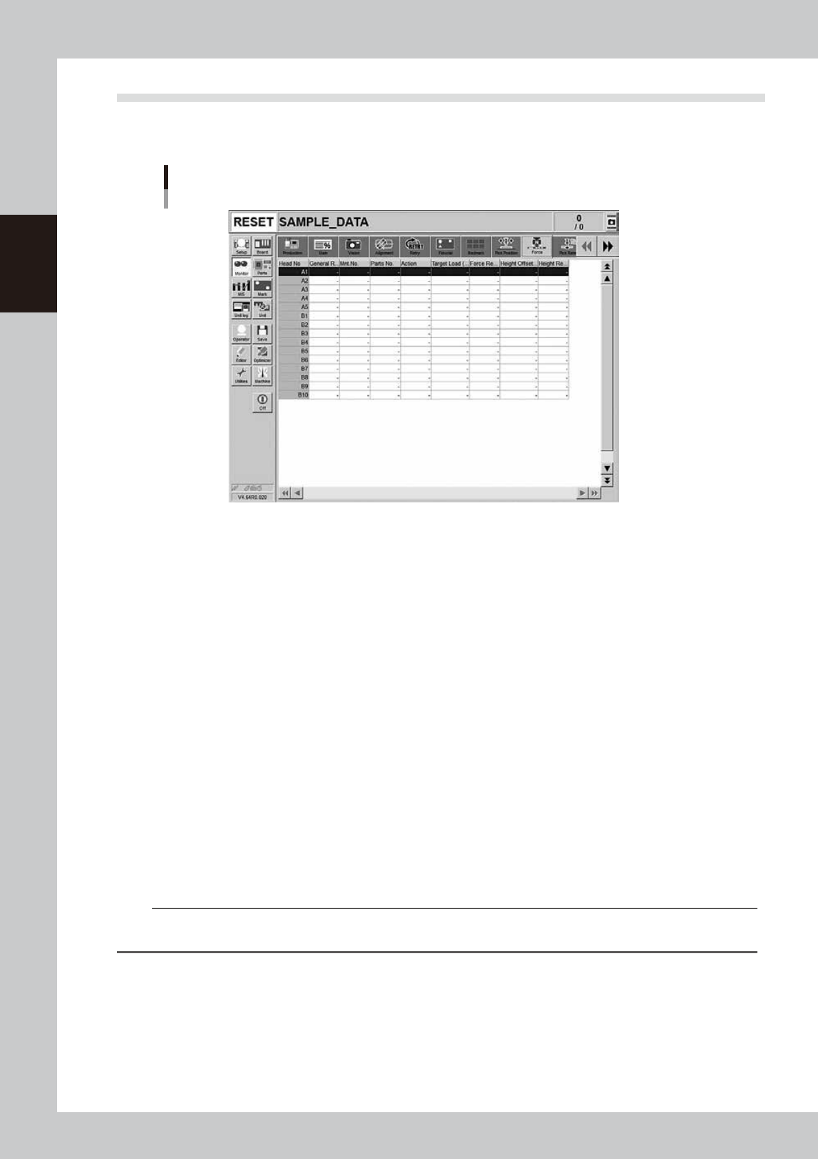
3.9 Force
This screen is displayed when the machine is equipped with a FM head. This screen shows the results at
real-time when using the force control.
Monitor: Force
24233-KMK-00
• Head No.
Displays the head number.
• General Result
Displays the general results of the force result and height result.
• Mnt. No.
Displays the mounting number.
• Parts No.
Displays the parts number.
• Action
Displays the force control execution action. (Pickup, dipping, mounting)
• Target Load (N)
Displays the target load (N).
• Force Result
Displays the force control result. The force control result shows NG if there is no board or component when executing
the force control.
• Height Offset (mm)
Displays the offset distance from the target coordinates. The upper portion shows the plus (+) direction.
• Height Result
Displays the result when the height offset (mm) result is compared with the error judgment distance.
n
NOTE
As the numeric value changes of the pickup, dipping, and mounting error judgment distances are the items in the
Machine Setting, the administrator level authority is needed.
2-35
2
Basic operation
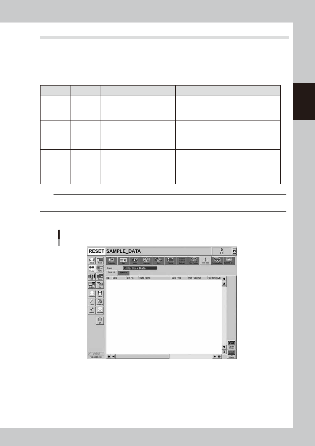
3.10 Pick Rate Warning
This screen appears when using the pickup rate warning function. When clicking the tab to switch the display,
the screen allows checking for a drop in the component pickup rate on each component or head.
The pickup rate is reset in real-time after mounting a group of components. However, if a particular component
or head is not used then its row will not appear on the display. Pickup rates can be monitored by color during
operation.
n
Display color
Color of row Status Pickup Rate Description
White 100% to [caution (yellow)]%
Pickup rate is above [caution (yellow)]% and below (or
equal to) 100%.
Yellow Caution [caution (yellow)]% to [warning (red)]%
Pickup rate is above [warning (red)]% and below (or
equal to) [Caution (yellow)]%.
Red Warning [warning (red)]% to 0%
Pickup rate is above (or equal to) 0% and below (or
equal to) [warning (red)]%.
If the machine setting of the stop control is set to “Use”,
the machine stops while generating an alarm. The
default setting is “Not Use”.
Pink
Watch-and-
wait mode
Optional
When the pickup rate is [warning (red)]% or less,
pressing the [Current Check] or [All Check] button
enables "watch-and-wait" mode and the color of the
"red" row(s) changes to "pink".
Note that operation is not stopped in this mode even if
stop control setting is made.
n
NOTE
Numerical values (%) in brackets [ ] are machine data setting items. Accessing such parameters require the
administrator level of authority.
[Parts Info] tab
Monitor: Pick Rate Warning
Parts info
24220-KMK-00
• No.
Displays the component No. (Parts screen data No.).
• Table
Displays the feeder table (feeder plate location) where the component feeder is installed.
• Set No.
Displays the feeder set position at which the component feeder is installed.
2-36
2
Basic operation
• Parts name
Displays the component name.
• Tape Type
The “Tape Type” shows the type of tape when the machine processes component tapes. It shows the method of supplying
components when processing tray components.
• Pick Rate (%)
Displays the pickup rate for each component. Rate is calculated by the following formula.
1 – ([Error count] ÷ [Number of components used]) = Pickup rate
• Feeder MACS
Displays the feeder MACS status.
• Offset X(mm), Y(mm)
Displays the offset amounts of the feeder MACS.
n
NOTE
The feeder MACS is a function that recognizes the mark at a specific location on the feeder to perform pickup offset
correction. This function normally applies to picking up components of 1005 or smaller.
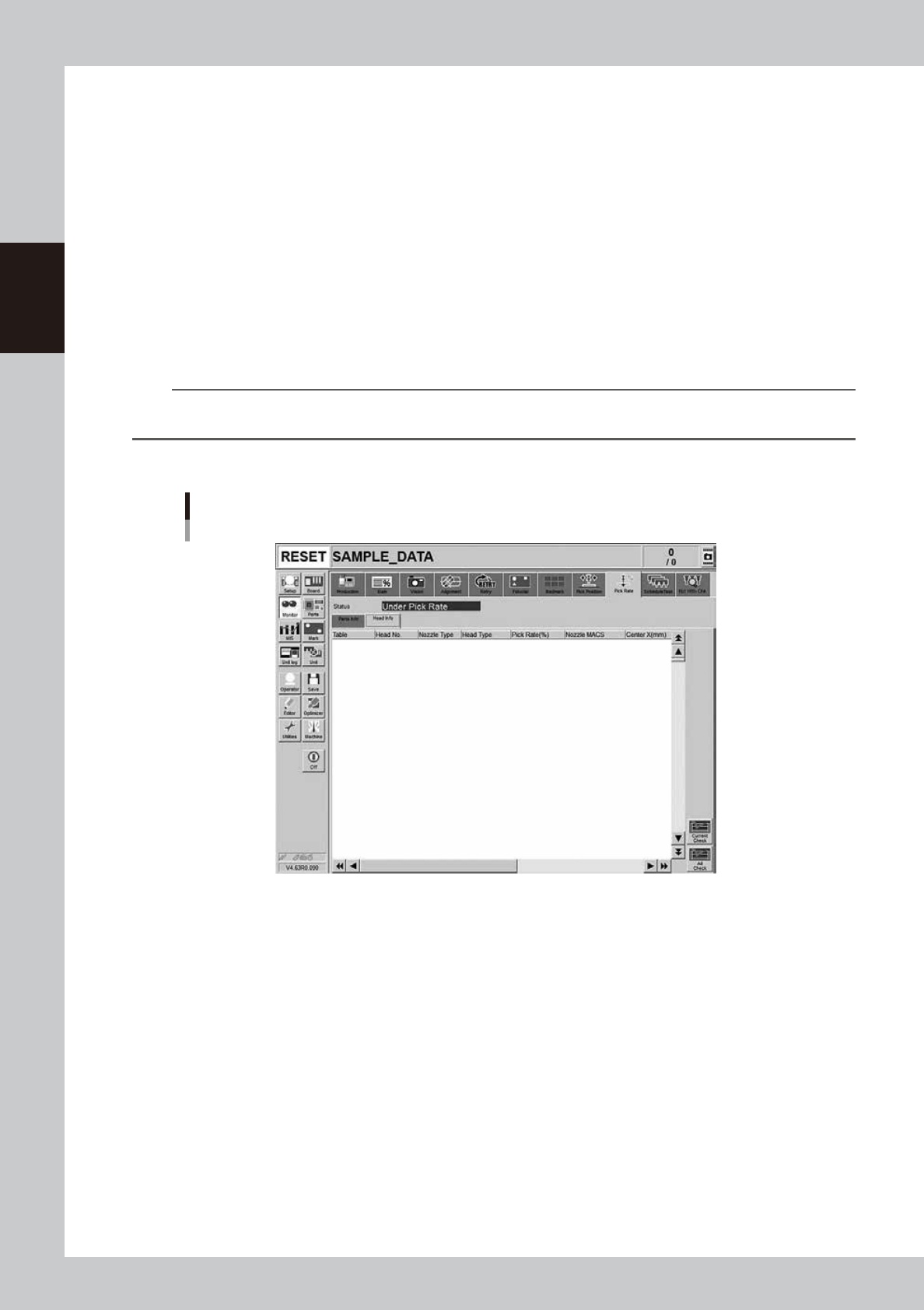
[Head Info] tab
Monitor: Pick Rate Warning
Head info
24221-KMK-00
• Table
Displays the corresponding table. This machine shows “Table A”.
• Head No.
Displays the head No. being used.
• Nozzle Type
Displays the current nozzle type.
• Head Type
Displays the method of changing the nozzle currently in use and other particulars such as automatic nozzle change and
manual nozzle change.
• Pick Rate (%)
Displays the pickup rate for each head. Rate is calculated by the following formula.
1 – ([Error count] ÷ [Number of components used]) = Pickup rate