EUKYX-199-3100_G5S2_Instruction_Vol3_E.pdf - 第102页
EUKYX 1-53 199-3100 5.15 Noz Lv ./Pos. Change window displ ay Pressi ng eac h button corresp ondi ng to each tea ch in g operation , changes o ver the wi ndow to the corresp ondi ng teac hi ng wi ndow . When the window i…
EUKYX
1-52199-3100
5.15 Noz Lv./Pos.
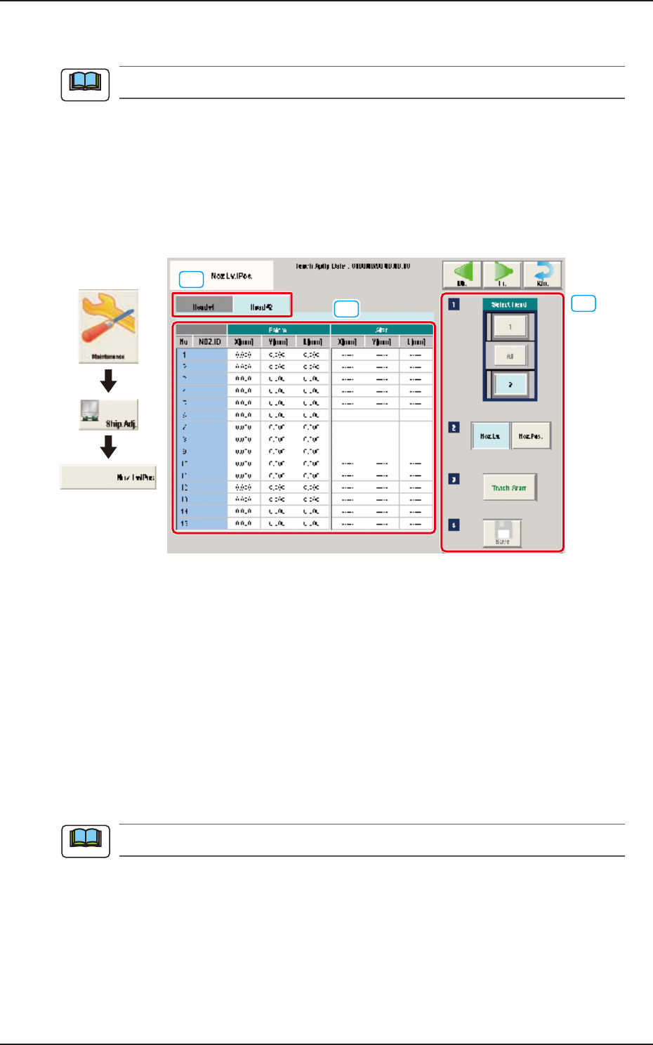
5.15 Noz Lv./Pos.
This window is not displayed when the multi-functional head is selected.
Noz.Lv.
This window enables you to perform teaching operations on the nozzle level (lower surface) offsets
of the ordinary nozzles on the heads.
Noz.Pos.
This window performs teaching operations on the deviations from the reference values between the
head rotational centers and the nozzle end positions.
[3]
[1]
[2]
Graphic
Development
F3A46
[1] Head Change Tabs
When each tab is pressed, the corresponding tab sheet for the head for each teaching operation,
appears.
[2] Teaching Data Display Section
Displayed are the teaching data items for the nozzle in the designated head.
[3] Teaching procedures section
The following buttons are arranged in teaching procedures section.
Select head
Select the head for the nozzle to be taught.
Select [All] when the teaching is performed for all the nozzles, .
When the head is selected with "Select Head" the window is changed accordingly.
Note
Note
EUKYX
1-53199-3100
5.15 Noz Lv./Pos.
Change window display
Pressing each button corresponding to each teaching operation, changes over the window to the
corresponding teaching window.
When the window is changed over, the teaching in the displayed window is performed.
The buttons corresponding to each window are as follows.
Noz. Lv. : The window is changed to the teaching window for the nozzle level.
Noz. Pos. : The window is changed to the teaching window for the reference nozzle position.
[Teach Start] button
Starts the teaching.
[Save] button
The teaching results are saved.
• Nozzle Level Teaching Procedure
(1) Select the head (1, 2 or All) for which the nozzle level offset teaching is performed.
(2) Press the [Teach Start] button. (When nozzle level will be measured using the side view
camera and the read data will be used as offset data.)
The teaching results are displayed in the "After" section in the "Noz Lv. Offset" Display Area.
When the teaching is completed, the designated head is returned to the home position
automatically.
(3) Press the [Save] button. (When this button is pressed, the teaching results are saved.)
• Nozzle Position Teaching Procedure
(1) Select the head and nozzle (from Head 1 or 2 and Nozzle 1 to 15) for which the nozzle
level offset teaching is performed.
(2) Press the [Teach Start] button. (The designated head (No. 1 or 2) is moved to the specified
position and the nozzle position offset teaching is executed.)
•
The teaching results are displayed in the “After” section in the “Noz Pos Offset” Display
Area.
• During this temporary stop mode, the selection of any other menu item is unavailable.
When the teaching is completed, the designated head is returned to the home position
automatically.
(3) Press the [Save] button. (When this button is pressed, the teaching results are saved.)
• Error Condition
When a nozzle recognition error occurs during the nozzle position offset teaching, the machine is
not stopped, but the teaching is continued to the end. The nozzle where an error occurred, is
skipped. The error existence can be confirmed in the “Recall” function.
Procedure
Note
Procedure
Note
EUKYX
1-54199-3100
5.16 Support pin Pos
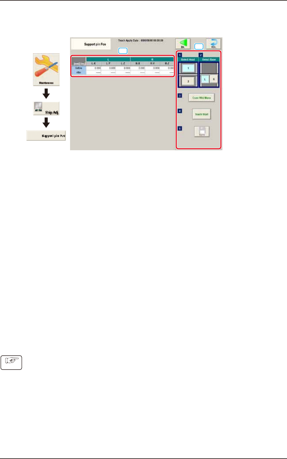
5.16 Support pin Pos
This window performs the teaching operation on the PCB support pin position.
[1]
[2]
Graphic
Development
F3A47
[1] Teaching Result
Before : Displayed are the offset values before the teaching operation.
After : Displayed are the offset values after the teaching operation.
[2] Operation buttons
Select Head
Select the head where the support pin position teaching is performed.
Select Base
Select the base where the support pin position teaching is performed.
[Conv Wid Move] Button
The head is evacuated and the conveyor width is extended to the limit.
[Teach Start] Button
The support pin position teaching is performed automatically.
[Save] button
The teaching results are saved.
• Teaching Jig
For the PCB support pin position teaching, the PCB support pin position teaching jig is used.
• Teaching Procedure
(1) Select the head to be used for the teaching.
(2) Select the base to be taught.
(3) Press the [Conv Wid Move] button. (The conveyor will move to the setup position.)
(4) Setup the PCB support pin teaching jig on the upper left and lower right.
(5) Press the [Teach Start] button. (The support pin position teaching is performed.)
(6) Press the [Save] button. (The teaching results are saved.)
Procedure