EUKYX-199-3100_G5S2_Instruction_Vol3_E.pdf - 第166页
EUKYX 2-18 199-3100 2.3 Feeder A / Feeder B [2] X (Horizont al) and Y (V e rtic al) [ mm] These of fse t parameters are used to ad ju st the position al devi ation based on the de si gn di m ensi ons representing the com…
EUKYX
2-17199-3100
2.3 Feeder A / Feeder B
2.3 Feeder A / Feeder B
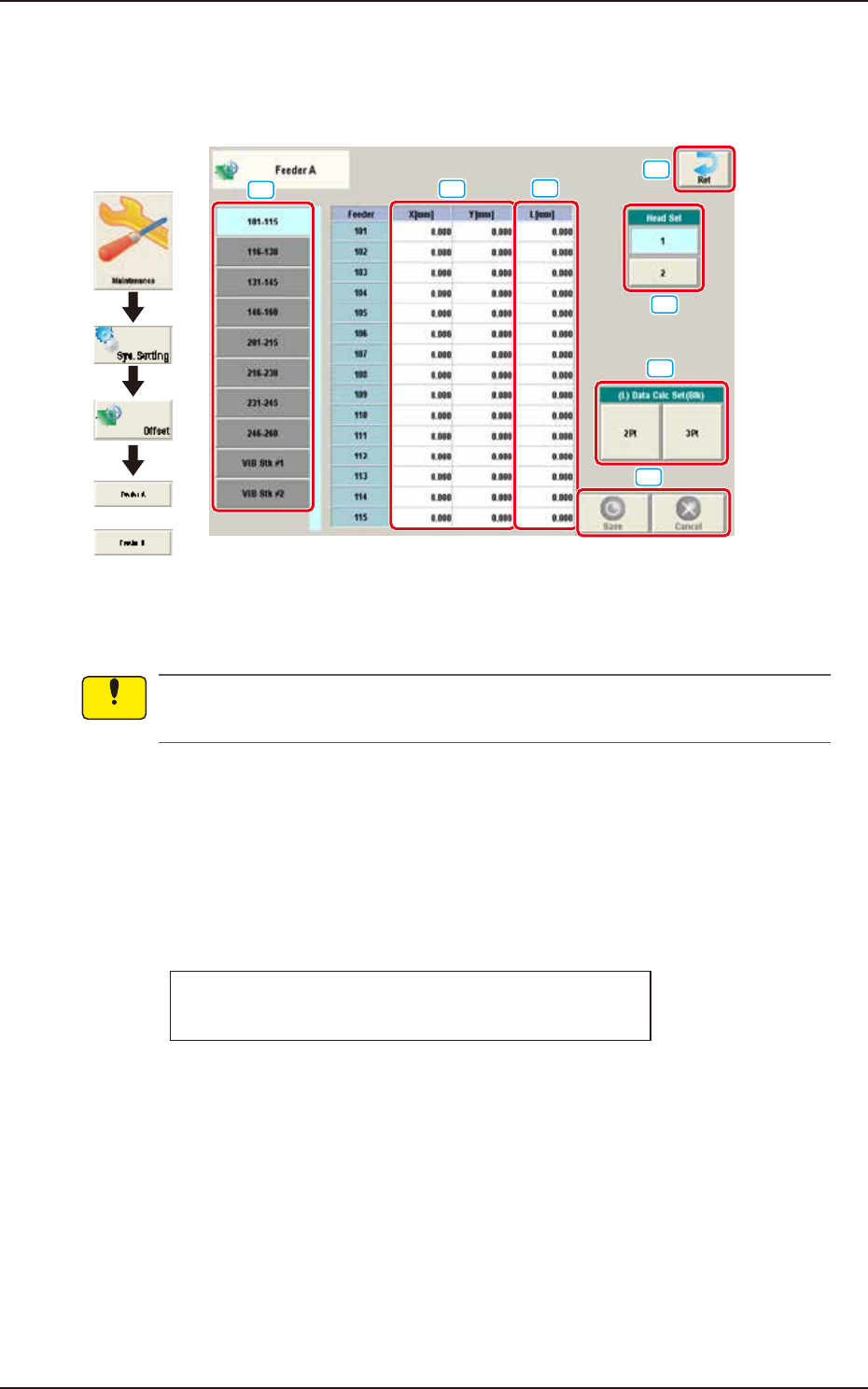
Pressing the [Feeder A] or [Feeder B] button on the "Offset Data" window displays the following
window.
or
Graphic
Development
[1]
[2]
[3]
[4]
[5]
[6]
[7]
F3B23A
Feeder Offset A
This offset data is used to correct variation in each feeder slot (Fdr No.) of the feeder base.
The parameters measured at shipment of the machine are entered.
Do not change the parameters unless necessary.
Feeder Offset B
This offset data is used to correct variation in the feeder.
• The X and Y parameters are recognition-processed during the automatic operation to track the
positional relation between the nozzle and component centers and updated automatically for
better pickup posture (pickup on the component center).
Note: In normal cases, it is not necessary to enter any parameters.
• The "L [mm]" parameters are not updated automatically but the entered ones are reflected.
Feeder offset parameters are added to actual offset values.
Actual Offset Values = Feeder (A) Offset + Feeder (B) Offset
[1] Feeder Change Tab
Another tab sheet can be opened by pressing the corresponding "Feeder Base" tab.
Notice
EUKYX
2-18199-3100
2.3 Feeder A / Feeder B
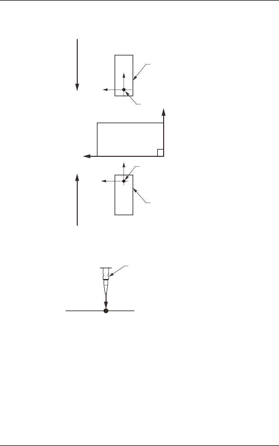
[2] X (Horizontal) and Y (Vertical) [mm]
These offset parameters are used to adjust the positional deviation based on the design dimensions
representing the component pickup position for each individual feeder slot Nos. (Fdr Nos.).
F211
F111
Rear Feeder
Front Feeder
Front Side of Machine
Y(+)
X(+)
Pickup Position
Pickup Position
Direction of Tape Feed
Direction of Tape Feed
F3B24
[3] L (Height) [mm]
Pickup Reference Level
Nozzle
L(+)
F3B25
When a value is entered with a plus (+) sign, the pickup height is reflected on the direction in
which the descending stroke of the nozzle will increase.
[4] [Ret] button
When this button is pressed, the “Offset Data” window is returned.
[5] Head Sel
Selects the head that calculates the feeder offset data automatically.
[6] (L) Data Calc Set (Blk)
The auto calculation methods of L data (teaching result offset value of pickup level) include “2Pt”
and “3Pt“. Pressing the [2Pt] or [3Pt] button calculates the L data of head 1 or head 2 on selected
block. The block is selected by changing the feeder with [1] Feeder Change tab.
[7] [Save] button
When this button is pressed, the input data is applied.
[Cancel] button
When this button is pressed, the input data is cancelled and window returns to the save data.
EUKYX
2-19199-3100
2.4 Beam
2.4 Beam
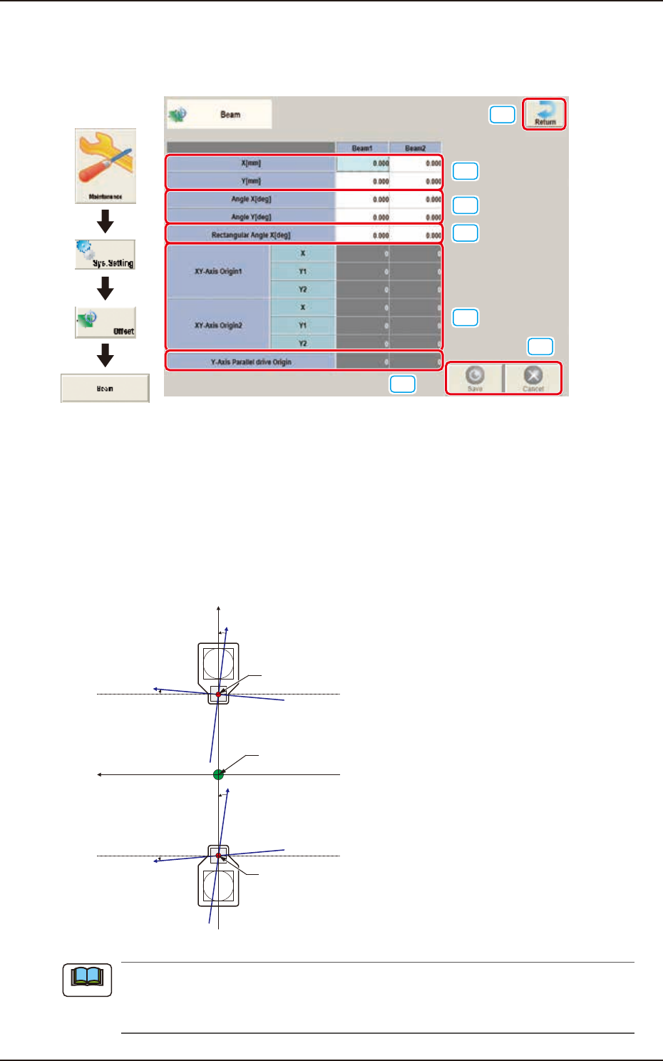
Pressing the [Beam] button on the "Offset Data" window displays the following window.
[1]
[2]
[3]
[6]
[7]
[4]
[5]
Graphic
Development
F3B26
[1] X (Horizontal) and Y (Vertical) [mm]
The set parameters are used to adjust the positional deviation based on the design dimensions
representing the distance between machine reference coordinate origin and center of the PEC
recognition camera at head origin.
[2] Angle X and Angle Y [deg]
The set parameters are used to adjust the beam X and Y axes to the machine reference coordinate
system.
Xm(+)
Ym(+)
Yb(+)
Xb(+)
Yb(+)
Xb(+)
Head Origin
Pm. Machine Reference
Coordinate Origin
Head Origin
Xm-Ym
Xb-Yb
: Machine Reference
Coordinate System
: Real Beam Coordinate
System
F3B27
A plus values must be entered in the “Angle X [deg]” and “Angle Y [deg]” text boxes when the
real beam coordinate system is tilted counterclockwise (based on the machine reference
coordinate system).
Note