EUKYX-199-3100_G5S2_Instruction_Vol3_E.pdf - 第131页
EUKYX 1-82 199-3100 6.3 RECOG 6.3.3 Capture Img. Pressi ng the [C apture Img .] tab on the [ RECOG] window di spla ys t he fol lowi ng window . Graphic Development F3A76 Sub T abs The "Capture Img. " window i s…
EUKYX
1-81199-3100
6.3 RECOG
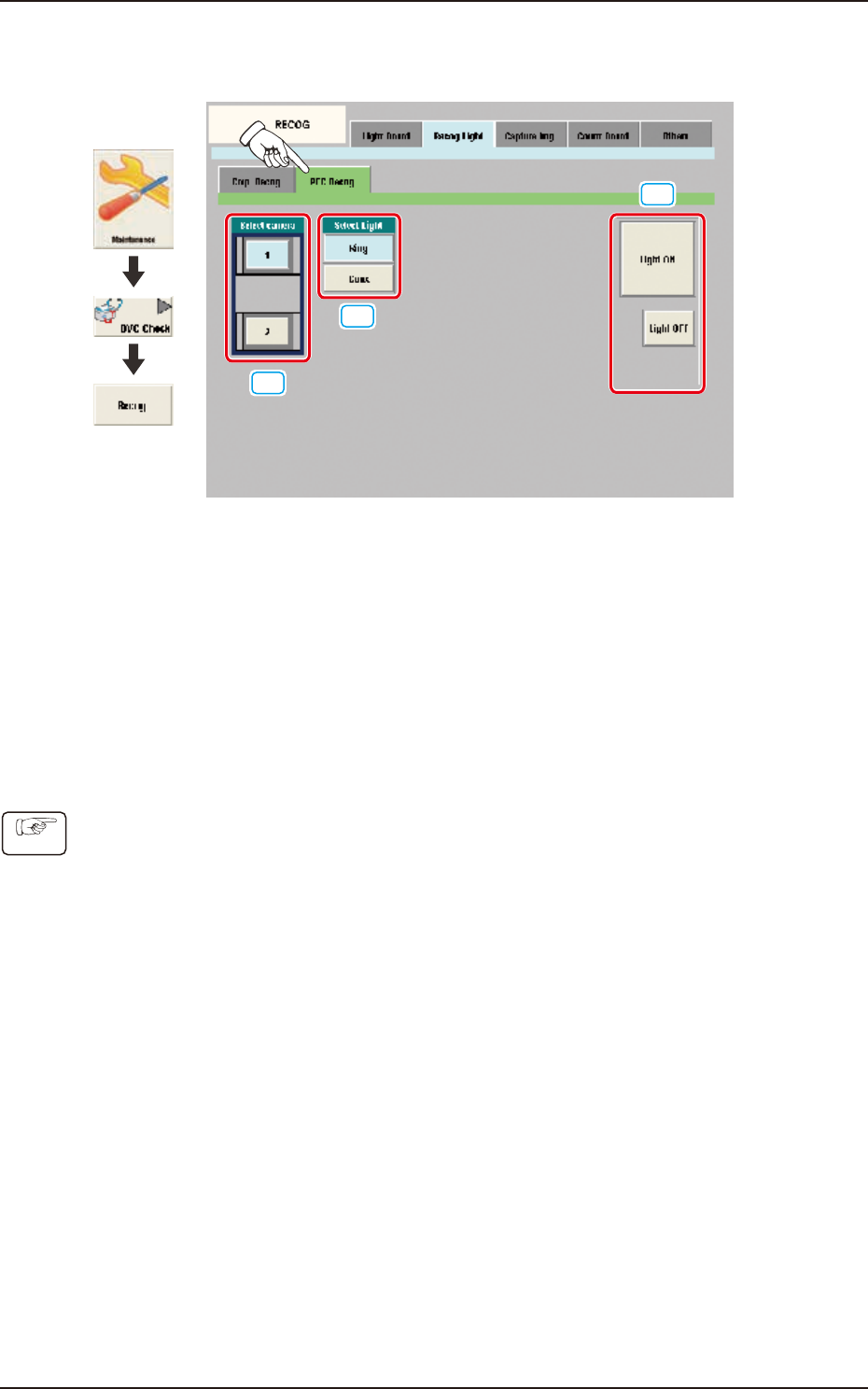
6.3.2.2 PEC Recog
Pressing the [PEC Recog] sub tab on the [Recog Light] tab displays the following window.
[1]
[2]
[3]
Graphic
Development
F3A75
[1] Select camera
Using these buttons, the PEC recognition camera to check the PEC recognition lighting, is selected.
[2] Select Light
Using these buttons, the lighting pattern to be checked is selected.
[3] [Light ON] Button / [Light OFF] Button
When this button is pressed, the lighting selected using "[2] Recognition Lighting Selection Buttons"
is turned ON or OFF.
• PEC Recognition Lighting Confirmation Procedure
(1) Using the button [1], select the PEC recognition camera with which the confirmation is to be
performed.
(2)
Using the button [2], select the lighting pattern with which the confirmation is to be performed.
(3) Using the button [3], select the lighting condition and confirm the lighting.
Procedure
EUKYX
1-82199-3100
6.3 RECOG
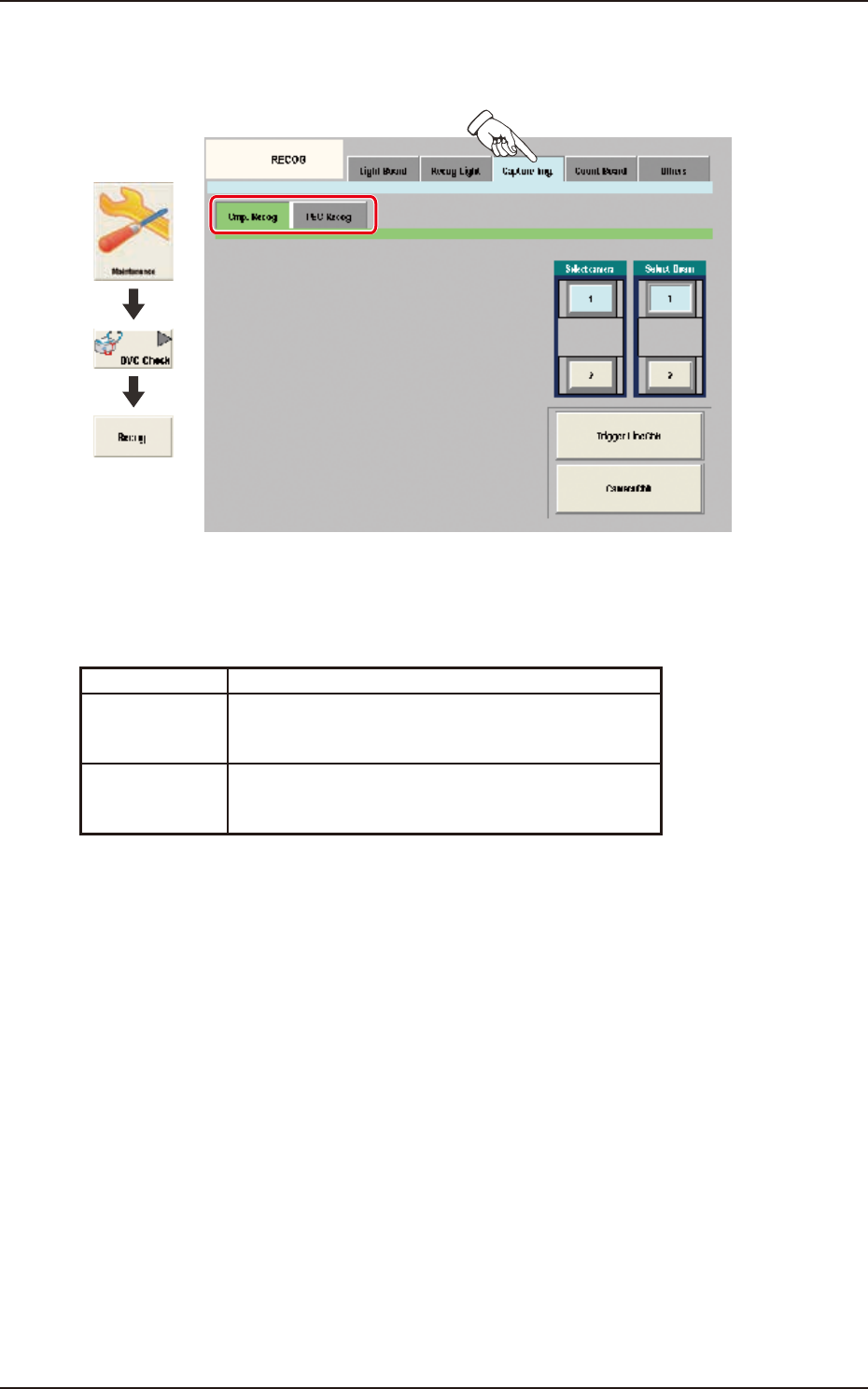
6.3.3 Capture Img.
Pressing the [Capture Img.] tab on the [RECOG] window displays the following window.
Graphic
Development
F3A76
Sub Tabs
The "Capture Img." window is provided with the following two tabs. When each tab is pressed, the
corresponding tab sheet appears.
Sub tab Description
Cmp. Recog In this tab sheet the image is captured using the
component recognition camera and the trigger line and
camera performance are checked.
PEC Recog In this tab sheet the image is captured using the PEC
recognition camera and the wire connection and camera
performance are checked.
EUKYX
1-83199-3100
6.3 RECOG
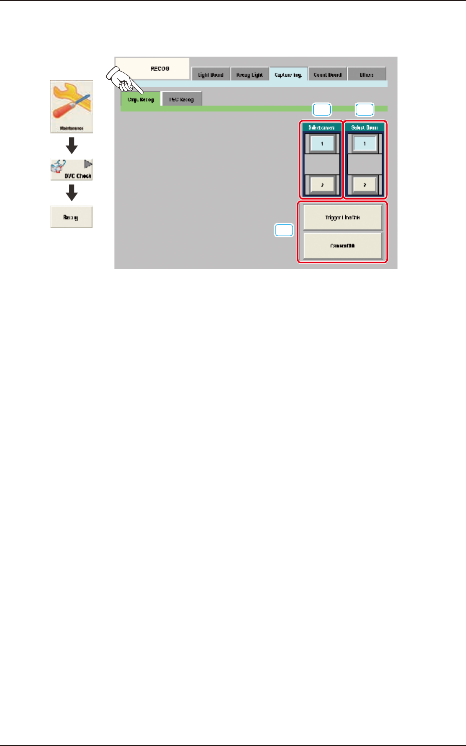
6.3.3.1 Cmp. Recog
Pressing the [Cmp. Recog] sub tab on the [Capture Img.] tab displays the following window.
[1]
[3]
[2]
Graphic
Development
F3A77
[1] Select camera
In this section the component recognition camera for capturing the component image is selected.
[2] Select Beam
In this section the beam to be checked is selected.
[3] Trigger Line Chk
Using this button, the trigger line for capturing the component image is checked.
Camera Chk
Using this button, the camera is checked.