EUKYX-199-3100_G5S2_Instruction_Vol3_E.pdf - 第74页
EUKYX 1-25 199-3100 5. Shipment Adj. But to n Na m e T eac hing Outline Sid e Vi ew C am er a T eac hes the side view camera attac hed to each placement head. NL-A x is Or g M as ter N oz Lv The te ach ing f or avoi din …
EUKYX
1-24199-3100
5. Shipment Adj.
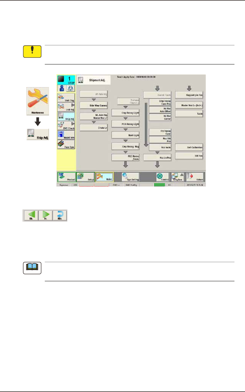
5. Shipment Adj.
In this window, the teaching operations to be performed when the machine is shipped from the
factory, are summarized.
In normal cases, it is not required to perform this teaching operation because the offsets are
factory-adjusted upon shipment of the machine.
Graphic
Development
MTN:NotRdy RCG:NotRdy
Cover
F3A22A
Common Operation Description
F3A23
[Bk.] Button
When this button is pressed, the window for the current items is changed to the one for the
previous Shipment Adjustment items.
As there is no previous items for the "Side View Camera" window, this button is not displayed
on the window.
[Fr.] Button
When this button is pressed, the window for the current items is changed to the one for the next
Shipment Adjustment items.
[Rtn.] Button
When this button is pressed, the window is changed to the one for the shipping adjustment initial
display window.
Notice
Note
EUKYX
1-25199-3100
5. Shipment Adj.
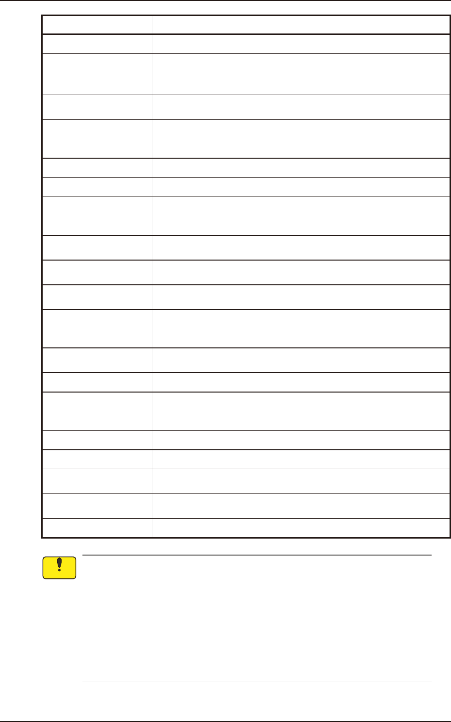
Button Name Teaching Outline
Side View Camera Teaches the side view camera attached to each placement head.
NL-Axis Org Master Noz
Lv
The teaching for avoiding the impact given to the component in the NL-axis
rotation and for the master nozzle lower surface level reference position are
performed.
Chute Lv
The head up/down offset is calculated automatically by teaching the chute
level when the head is changed.
Cmp Recog Light Teaches the lighting for the component recognition camera.
PCB Recog Light Teaches the lighting for the PCB recognition camera.
Mark Light Teaches the Mark Light.
Cmp Recog Mag Teaches the magnification of component recognition camera.
PEC Recog_Beam
Teaches the PEC recognition camera offsets (Magnifications X (Horizontal),
Y (Vertical) and Z (Angle) and the beam offsets (Beam X (Horizontal), Beam
Y (Vertical), Beam Angle X and Beam Angle Y).
Cmp Recog Camr Pos
Teaches the component recognition camera position (X (Horizontal), Y
(Vertical) and Z (Angle) are performed.
Hd Rot Axis Offset
Teaches the designed distance from the locating position reference to the
camera center based on the placement position reference.
Hd Rot Center
Teaches to correct the deviation of the head rotation center from the PEC
recognition camera center reference value using the jig component.
Fly Recog Camr
The image capture timing is taught after finding the deviation of component
recognition camera position in stopped image shooting, from the position in
fry recognition image capturing.
Noz Stk Pos
Teaches for keeping the nozzle stocker position (machine coordinate
reference).
Noz Incln Teaches the offset data to collect the head/nozzle inclination.
Noz Lv/Pos.
Teaches the nozzle lower surface level for the normally attached nozzle and
for the deviation of the head rotation center to the nozzle end position to the
head from the reference values.
Support pin Pos Teaches the PCB support pin position (X-axis, Y-axis).
Master Noz Lv (Indv.) Teaches the master nozzle level individually.
Table
Teaches the deviation amount (X and Y) when the head moves from the
PCB positioning reference to the grid (X and Y).
Self Calibration
Measures placement accuracy in the machine automatically and feeds back
to offset data.
Slit Pos Teaches the slit position on backup base.
• The teaching operation might affect the component placement accuracy. Therefore,
contact YAMAHA sales representatives.
• Some operations require special jigs (options).
Contact YAMAHA sales representatives before performing any teaching operations.
• Follow the teaching procedures in the specified order. Otherwise, some trouble (such as
inaccurate component placement, frequent mechanical errors, etc.) will arise.
• Before performing any teaching operation, confirm that the component recognition offset
jig, the jig setting position, and the back light stage (teaching plate) are not nicked and
stained.
Notice
EUKYX
1-26199-3100
5. Shipment Adj.
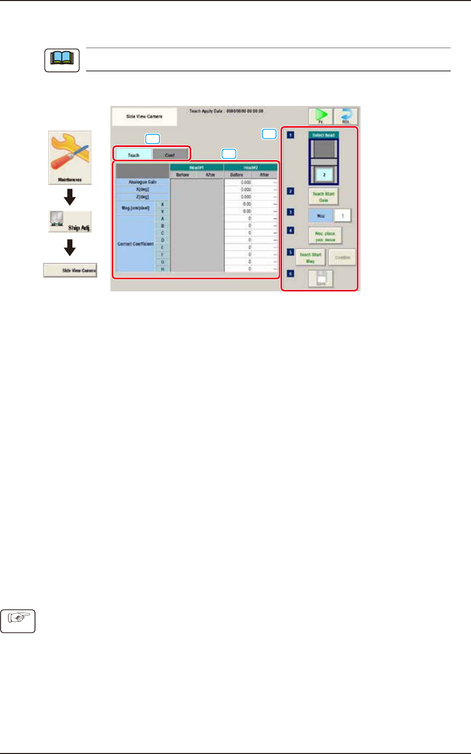
5.1 Side View Camera
This window is not displayed when the multi-functional head is selected.
The teaching is performed for side view cameras on each head.
[1]
[3]
[2]
Graphic
Development
F3A97
[1] “Teach/Conf" tabs
Switches the "Teach" window and "Conf" window.
[2] Teach/Conf window
The offset of side view camera on specified head is displayed.
Selecting "Teach" tab displays the "Teach" window. Selecting "Conf" tab displays the "Conf" window.
[3] Teaching procedures section
The following buttons are arranged in teaching procedures section.
Select head:
Selects the head to be taught.
[Teach Start Gain] button:
Performs gain teaching.
[Noz] button:
Press the [Noz] button to open the window to select the nozzle to be taught.
[Noz. place. pos. move] button
Pressing the button turns the specified nozzle to move to the machine front side when
attaching/detaching nozzle.
[Teach Start Mag.] button:
This button is not currently used.
[Confirm] button:
Performs the confirmation.
[Save] button:
Saves the teaching results.
■
Procedures for gain teaching
(1) Select the head (1 or 2) to be taught.
(2) Press the [Teach Start Gain] button and then press the [START] button on the operation
panel within 10 seconds. The gain teaching is performed.
(3) After teaching, the value is displayed in the “After” cell of “Analogue Gain”.
(4) Press the [Save] button to save the teaching result.
Note
Procedure