EUKYX-199-3100_G5S2_Instruction_Vol3_E.pdf - 第169页
EUKYX 2-21 199-3100 2.4 Beam [ 4] XY -Ax is Origin 1 and 2 The set parameters are used to mai ntai n the beam conditi on (p ositi on ) set up right a fter t he mac hi ne was assem bl ed. Use the va lues fed ba ck aut oma…
EUKYX
2-20199-3100
2.4 Beam
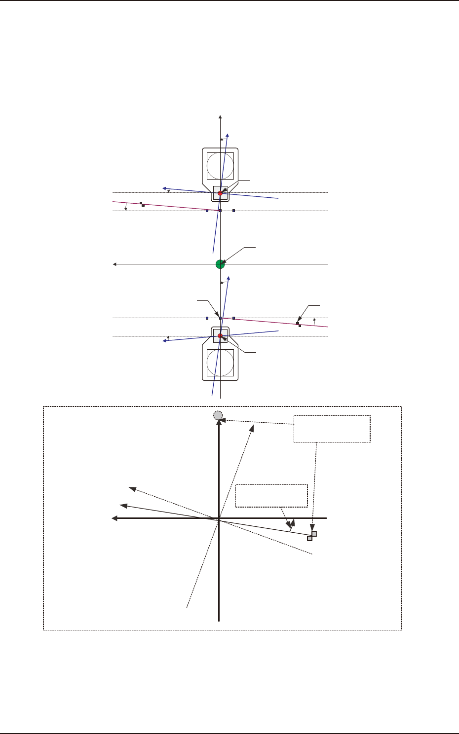
[3] Rectangular Angle X [deg]
These parameters represent the amount of angular deviations (X directions) of the mark on the
machine in comparison with the X directions in the machine reference coordinate system.
The set parameters are used to check the three marks on the area of the machine where only a little
positional change can be made according to temperature changes and adjust the beam X/Y axes
such that they can cross at right angles.
Xm(+)
Ym(+)
Yb(+)
Xb(+)
Yb(+)
Xb(+)
Xm'
Machine Reference
Coordinate System
Mark Coordinate
System
Beam Coordinate
System
Mark on Machine
Rectangular Angle
X [deg]
Head Origin
Pm. Machine Reference
Coordinate Origin
Standard Mark 2
Head Origin
Standard Mark 1
Xm-Ym
Xb-Yb
: Machine Reference
Coordinate System
: Real Beam Coordinate
System
F3B28
EUKYX
2-21199-3100
2.4 Beam
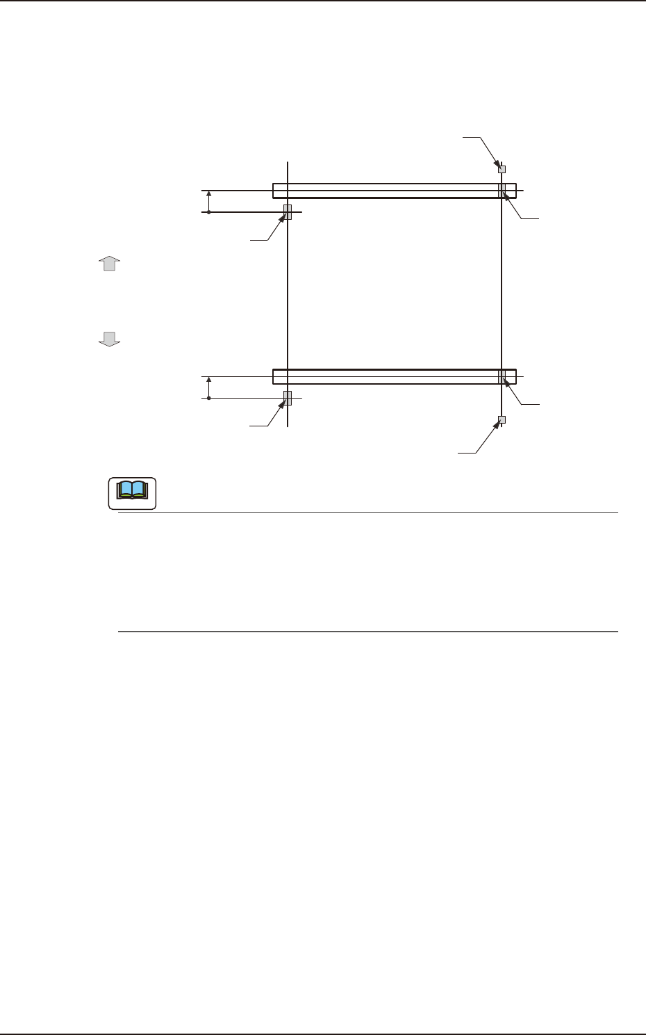
[4] XY-Axis Origin 1 and 2
The set parameters are used to maintain the beam condition (position) set up right after the machine
was assembled.
Use the values fed back automatically from the motion controller after the Y-axis is zeroed
(adjustment mode).
Master SideSlave Side
Origin Mark
(Origin Signal Position)
Beam
Beam
Zeroing
Direction
Zeroing
Direction
Y-Axis Origin Offset
= (+) Value
Limit Sensor
Y-Axis Origin Offset
= (+) Value
Origin Mark
(Origin Signal Position)
Origin Mark
(Origin Signal Position)
Origin Mark
(Origin Signal Position)
Limit Sensor
F3B29
Note
(a) The displayed parameters cannot be edited manually.
(b) The Y-axis origin offset indicates where the origin signal position of the master axis is
located when viewed in the zeroing direction from the origin signal position of the slave
axis. A plus sign will be affixed when the origin signal position is located in the same
direction as the zeroing one. When it is located in the opposite direction, a minus sign is
affixed.
[5] Y-Axis Parallel Drive Origin
Displays the offset value of origin signal position of the automatically adjusted Y-axis parallel drive
axis (master axis and slave axis).
[6] [Return] button
When this button is pressed, the window returns to the "Offset Data" window.
[7] [Save] button
When this button is pressed, the input data is applied.
[Cancel] button
When this button is pressed, the input data is cancelled and window returns to the save data.
EUKYX
2-22199-3100
2.5 Head
2.5 Head
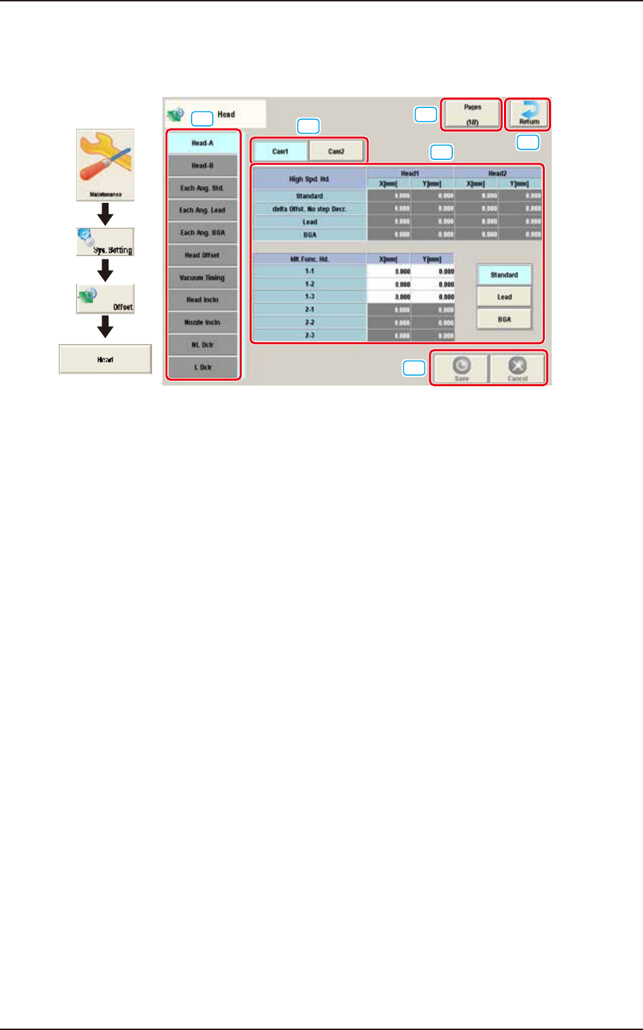
Pressing the [Head] button on the "Offset Data" window displays the following window.
Graphic
Development
[1]
[5]
[6]
[2]
[3]
[4]
F3B30A
[1] Offset button
When this button is pressed, the offset data for the selected tab is displayed.
[2] Offset Data Display Section
In this section, the offset data selected in step [1] is displayed.
[3] Page Change Button
Using this button, the offset editing page is changed.
[4] [Return] button
When this button is pressed, the window returns to the "Offset Data" window.
[5] [Save] button
When this button is pressed, the input data is saved.
[Cancel] button
When this button is pressed, the input data is cancelled and window returns to the save data.
[6] [Cam1] / [Cam2] button
Switches the component recognition camera.