EUKYX-199-3100_G5S2_Instruction_Vol3_E.pdf - 第52页
EUKYX 1-3 199-3100 2. MAINTENANCE 2. M AI NTENANCE Thi s wi ndow enab les you t o adj ust t he mac hi ne, check the per formanc e, and perform vari ous teach ing operati ons. When the [Maint.] button in the "TOP&quo…
EUKYX
1-2199-3100
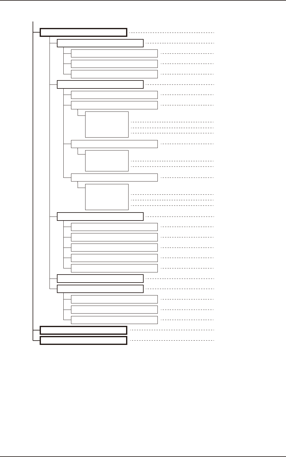
1. Outline of Menus for Maintenance
(Continued from previous page. )
[Sub buttons]
DVC Check
Reference Item Nos.
6.1.1
6.1
InP Chk
InP/OutP
6
6.1.2OutP Chk
6.1.3List Dsp
6.2.1
6.2
Operation
Motor
6.2.2
(1)
(2)
(3)
Sys Info
System #1 to #4
Axis dt #1 to #4
Servo amp ...
6.3.1
6.3
Light Board
Recog.
6.4
Com.Stat
6.3.2Recog Light
6.3.3Capture Img.
6.3.4Count Board
6.3.5Others
6.5.1
6.5
Application
Prgm.Info.
7
MAINT WN
8
Pass Opn.
6.5.2MC Info
6.5.3Setup Log
[Tabs]
6.2.4
(1)
(2)
(3)
List
Normal
Multi-HD
Firmware
[Tabs]
6.2.3
(1)
(2)
DI stop
State monitor
Parameter
F3A2
EUKYX
1-3199-3100
2. MAINTENANCE
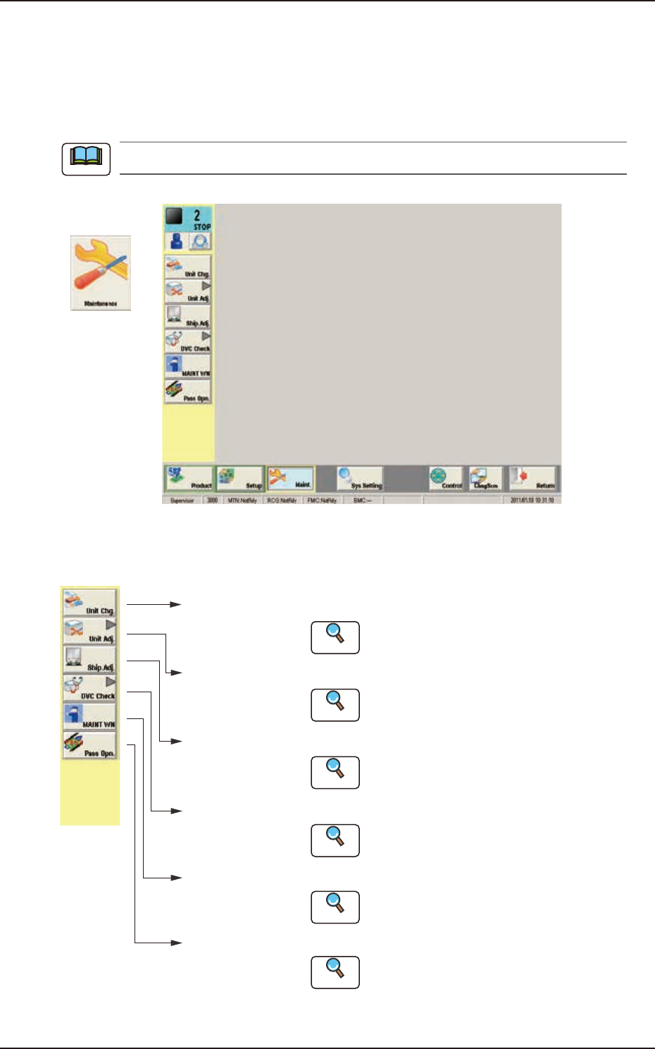
2. MAINTENANCE
This window enables you to adjust the machine, check the performance, and perform various
teaching operations. When the [Maint.] button in the "TOP" page is pressed and the logging-in
operation is performed, the "Maintenance" window appears.
The indication on the window varies depending on the user's access authorization .
Graphic
Development
F3A3
The [Maintenance] main menu buttons are arranged to display the operation windows where each
function in the Machine Maintenance (SPECIAL SEL) is executed.
[Unit Chg.]
Button
Open the "Unit Change" window.
Open the "Unit Adj." submenu.
Open the "Shipment Adj." window.
Open the "DVC Check" submenu.
[Unit Adj.]
Button
[Ship.Adj.]
Button
[DVC Check]
Button
:
:
:
:
Reference
Reference
Reference
Reference
Open the "MAINTWM" window.[MAINT WN]
Button
:
Reference
Open the "Pass Opn." window.[Pass Opn.]
Button
:
Reference
Refer to "3. Unit Change" in Chapter 1
for details.
Refer to "4. Unit Adj." in Chapter 1 for details.
Refer to "5. Shipment Adj." in Chapter 1
for details.
Refer to "6. DVC Check" in Chapter 1
for details.
Refer to "7. MAINTWM" in Chapter 1 for
details.
Refer to "8. Pass Operation (for Emergency)."
in Chapter 1 for details.
F3A4
Note
EUKYX
1-4199-3100
3. Unit Change
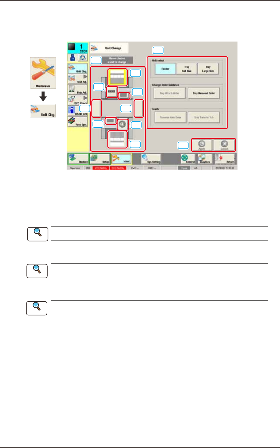
3. Unit Change
This window enables the operator to perform the unit change in the system.
[1]
[2]
[3]
[3]
[2]
[4]
[4]
[5][5]
[6]
[7]
Graphic
Development
F3A5A
[1] Unit Image Button
Shown are the image buttons for each unit and when the button for the unit to be changed is
pressed, the "Unit Operation Button" is changed.
[2] Head Unit Button
Refer to “3.1 Head Unit” in this chapter for the details.
[3] Nozzle Stocker Button
Refer to “3.2 Nozzle Stocker” in this chapter for the details.
[4] Feeder Unit Button
Refer to “3.3 Feeder Unit” in this chapter for the details.
[5] Conveyor Button
This button is optional.
[6] Unit Operation Button
The operation button for the unit selected using the unit image button, is displayed. The indication
is changed depending on the selected unit.
[7] [Apply] Button and [Cancel] Button
[Apply] Button : When pressed, this button applies the changed unit to the production line
configuration.
[Cancel] Button : When pressed, this button cancels the changed unit and returns it to the unit
before change.
Reference
Reference
Reference