EUKYX-199-3100_G5S2_Instruction_Vol3_E.pdf - 第78页
EUKYX 1-29 199-3100 5.4 Cmp Recog Light 5.4 Cmp Recog Ligh t The correspondin g wi ndow enab les you t o per form a teach ing operati on on the li ghting of the component recogn itio n camera. [1] [2] [4] [3] Graphic Dev…
EUKYX
1-28199-3100
5.3 Chute Lv (Shipment/exchange)
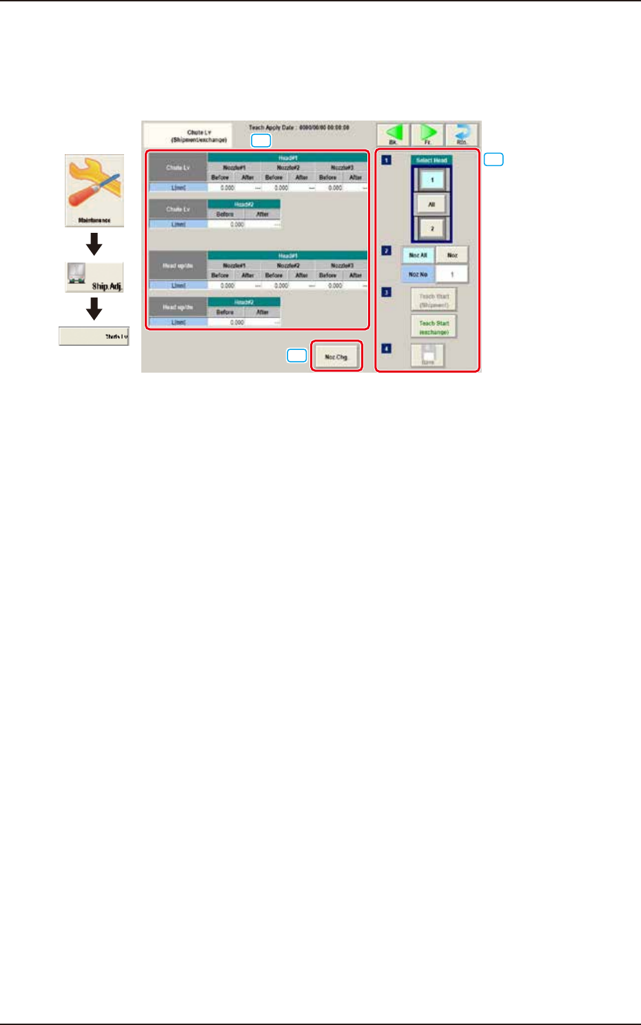
5.3 Chute Lv (Shipment/exchange)
This teaching function enables the operator to calculate the head up/down offset on this window,
by means of measuring the chute level when the head is changed, and calculating a difference
between the values before and after head change.
[1]
[3]
[2]
Graphic
Development
F3A26
[1] Teaching Data Display Section
Chute Lv Head Up Down
The data measured before the machine delivery is displayed in the "Before" data box.
[2] [Noz. Chg.] Button
The nozzle is changed.
[3] Select Head
Selects the head to be taught.
[Noz All] Button
The teaching for all the nozzles is performed.
[Noz] Button
Specifies the nozzle to be taught.
When the [Nozzle] button is pressed, the data input window appears.
[Teach Start] Button
The teaching is performed.
[Save] Button
The teaching results are saved.
EUKYX
1-29199-3100
5.4 Cmp Recog Light
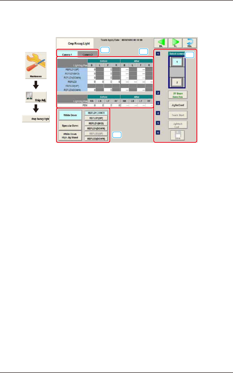
5.4 Cmp Recog Light
The corresponding window enables you to perform a teaching operation on the lighting of the
component recognition camera.
[1]
[2]
[4]
[3]
Graphic
Development
F3A27
[1] Camera Selection Tab
When either of the tabs is selected, the camera to be taught is selected.
[2] Teaching Data Display Section
Displayed are offset data items for each lighting pattern for the designated camera.
[3] Lighting Pattern Selection
The lighting pattern is selected from the following items.
[White Down] Button
"REFLD 1,3 PATT", "REFLD 1 (UP)", "REFLD1 (MID)", "REFLD 1 (DOWN)", "REFLD 3 (UP)",
"REFLD 3 (DOWN)"
[Specular Down] Button
"REFLD 2"
[White Down High Jig Stand] Button
"PEN"
EUKYX
1-30199-3100
5.4 Cmp Recog Light
[4] Teaching procedures section
The following buttons are arranged in teaching procedures section.
Select camera
Selects the camera to be taught.
[XY Beam Save Pos] Button
Moves the XY beam to the escape position.
[Jig Set Conf]
Confirms the jig attachment.
[Teach Start] Button
Teaches the selected camera.
[Jig Detach Conf]
Confirms the jig removal.
[Save] Button
The teaching results are saved.
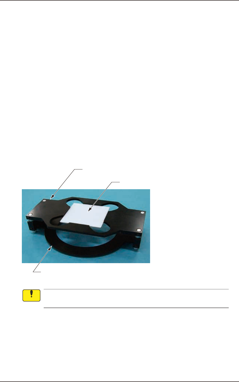
• Teaching Jig for Component Recognition Camera Lighting
The following jigs are used for teaching on the component recognition camera lighting. Before
teaching, combine the jig with the teaching glass jig mounting support jig and place it on the PEC
recognition camera. After the teaching operation, remove it.
Teaching Glass Jig Mounting Support Jig 1
Teaching Glass Jig
Teaching Glass Jig Mounting Support Jig 2 (High Base Jig)
(JG-0287,KYF-M8840-00)
(JG-0286,KYF-M8830-00)
F3A28
Set-up the teaching glass jig mounting support jig securely so that it does not rise. If the
mounting condition is not satisfactory, the head, etc., might be damaged.
Notice