EUKYX-199-3100_G5S2_Instruction_Vol3_E.pdf - 第133页
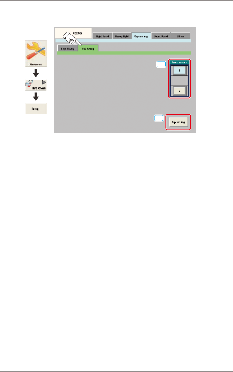
EUKYX 1-84 199-3100 6.3 RECOG 6.3.3.2 P EC Rec og Pressi ng the [PEC Recog] sub tab on t he [ Capture Img .] tab displ ays the fo l low ing w indo w . [1] [2] Graphic Development F3A78 [ 1 ] Se lect cam era In thi s sec …
EUKYX
1-83199-3100
6.3 RECOG
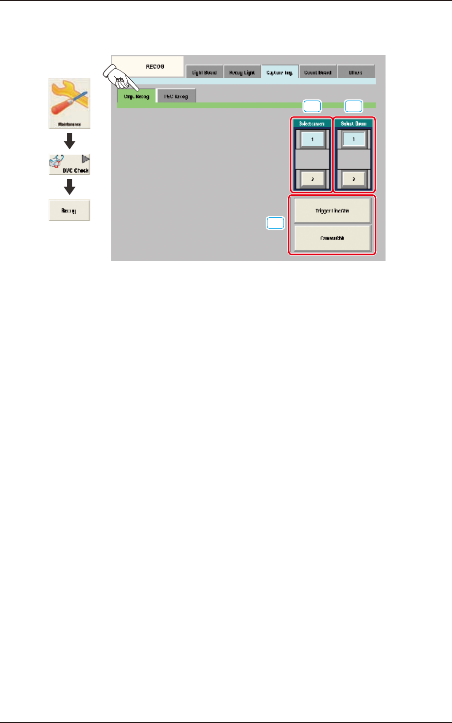
6.3.3.1 Cmp. Recog
Pressing the [Cmp. Recog] sub tab on the [Capture Img.] tab displays the following window.
[1]
[3]
[2]
Graphic
Development
F3A77
[1] Select camera
In this section the component recognition camera for capturing the component image is selected.
[2] Select Beam
In this section the beam to be checked is selected.
[3] Trigger Line Chk
Using this button, the trigger line for capturing the component image is checked.
Camera Chk
Using this button, the camera is checked.
EUKYX
1-84199-3100
6.3 RECOG
6.3.3.2 PEC Recog
Pressing the [PEC Recog] sub tab on the [Capture Img.] tab displays the following window.
[1]
[2]
Graphic
Development
F3A78
[1] Select camera
In this section, the PEC recognition camera for capturing the component image is selected.
[2] [Capture Img.] Button
Using this button, the image is captured using the selected camera.
EUKYX
1-85199-3100
6.3 RECOG
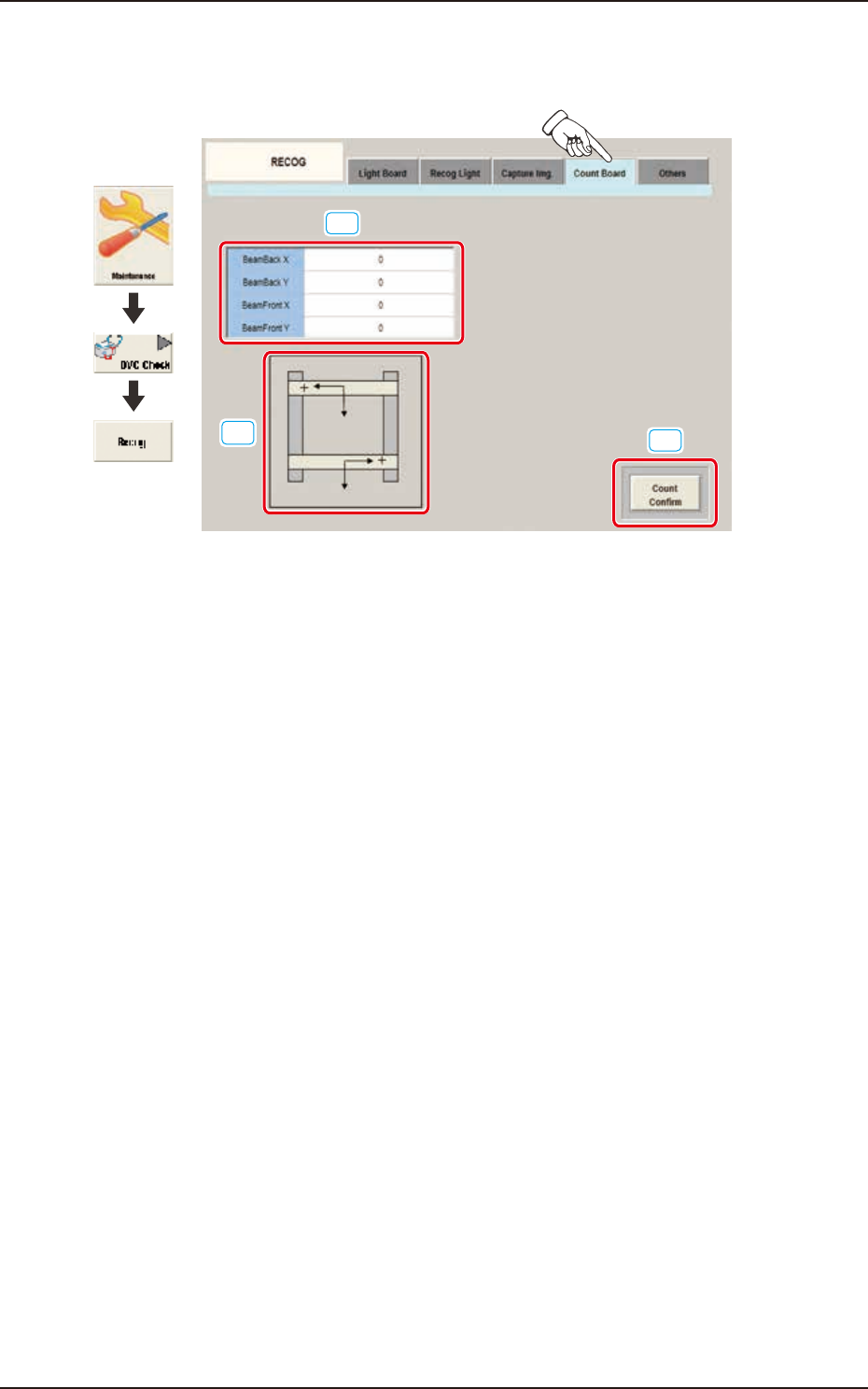
6.3.4 Count Board
Pressing the [Count Board] tab on the [RECOG] window displays the following window.
[1]
[2]
[3]
Graphic
Development
F3A79
[1] BeamBack X, Y / BeamFront X, Y
In these data boxes the X, Y count values are displayed for each beam.
[2] XY Beam Image
Displayed are the X and Y beam images.
[3] [Count Confirm] Button
When this button is pressed, the current counter value is checked.
The change position and increase/decrease direction of the count value displayed by means of
pressing the beam manually and pressing the [Count Confirm] button, are confirmed.