EUKYX-199-3100_G5S2_Instruction_Vol3_E.pdf - 第164页
EUKYX 2-16 199-3100 2.2 Feeder Base 2. 2 Feeder Base Pressi ng the [Fe eder bas e] but ton on the "O f fset Data" wi nd ow di spla ys the foll owi ng window . [1] [2] [3] Graphic Development F3B22 [ 1 ] L [mm ]…
EUKYX
2-15199-3100
2.1 Device Offset
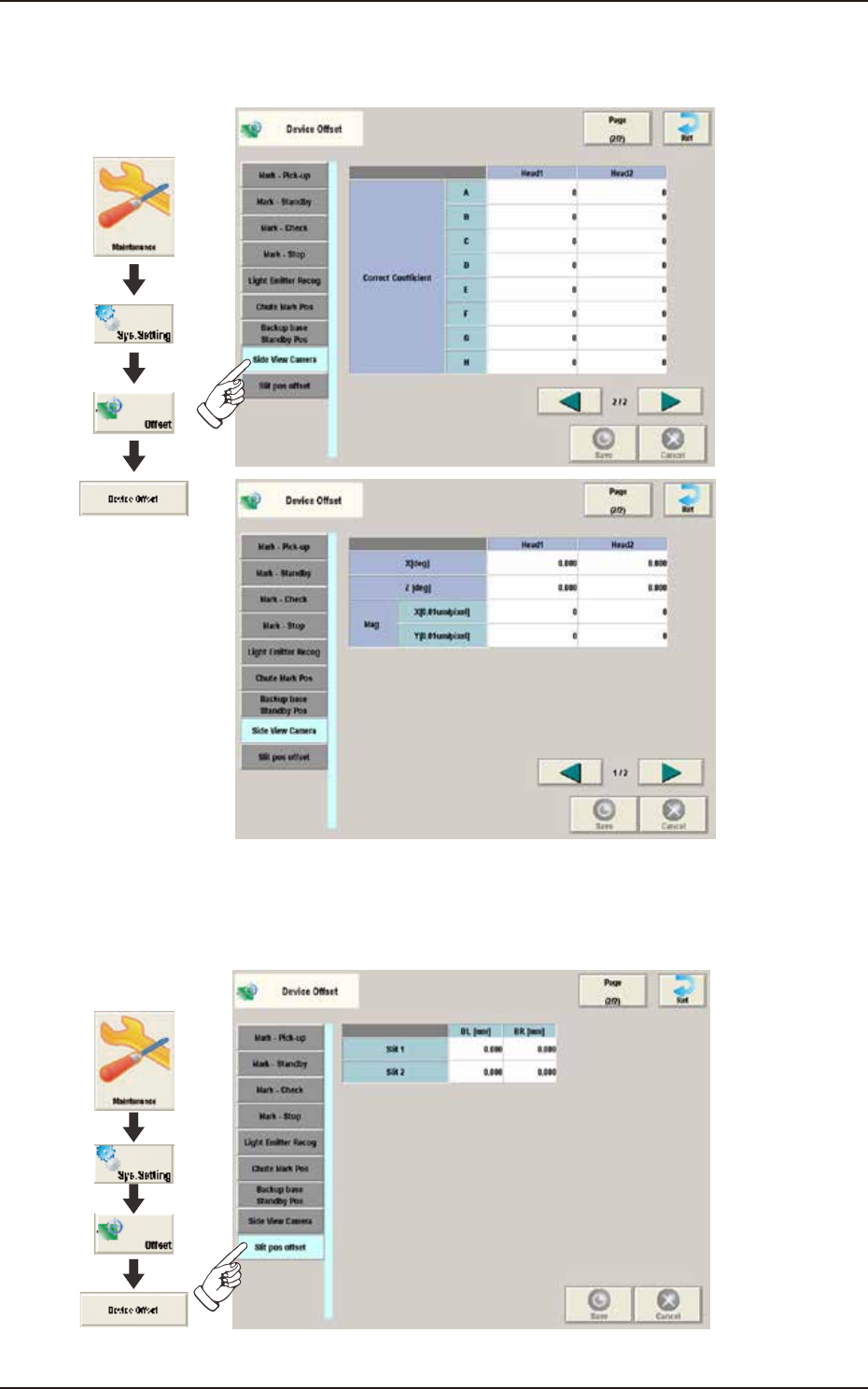
2.1.17 Side View Camera
Pressing the [Side View Camera] tab on the "Device Offset" window displays the following window.
Graphic
Development
F3B90A
2.1.18 Slit Pos Offset
Pressing the [Slit Pos Offset] tab on the "Device Offset" window displays the following window.
Graphic
Development
F3B91A
EUKYX
2-16199-3100
2.2 Feeder Base
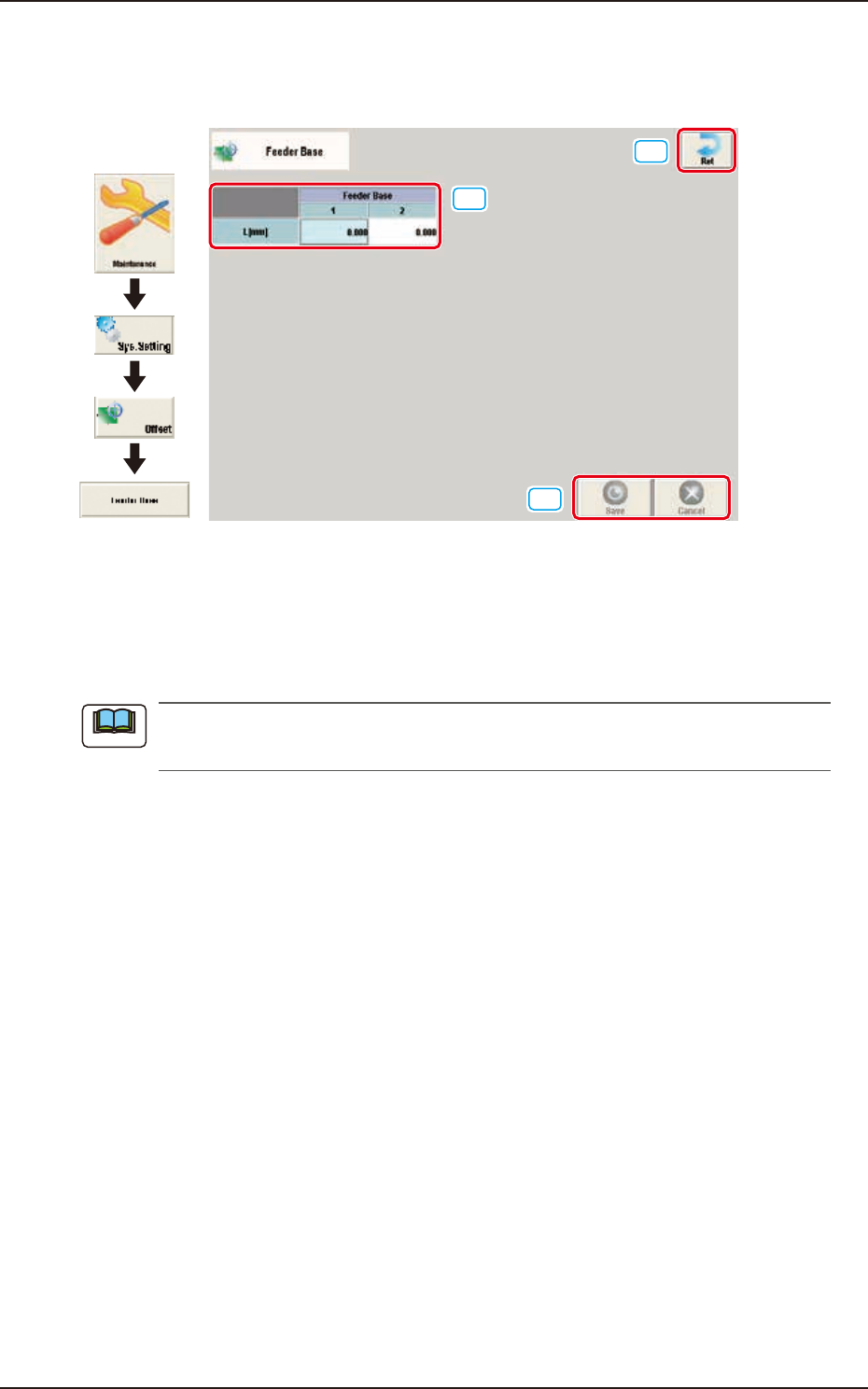
2.2 Feeder Base
Pressing the [Feeder base] button on the "Offset Data" window displays the following window.
[1]
[2]
[3]
Graphic
Development
F3B22
[1] L [mm]
The set offset parameters are used to adjust the positional deviations (height direction) based on the
design dimensions of Feeder Bases #1 and #2. When the feeder bases are installed lower than the
design values, a plus value must be entered in each text box.
The tilts of the PCB positioning sections on the feeder base sections are calculated on the X
and Y values of "Mark (Left)" and "Mark (Right)".
[2] [Ret] button
When this button is pressed, the window returns to the "Offset Data" window.
[3] [Save] button
When this button is pressed, the input data is applied.
[Cancel] button
When this button is pressed, the input data is cancelled and window returns to the save data.
Note
EUKYX
2-17199-3100
2.3 Feeder A / Feeder B
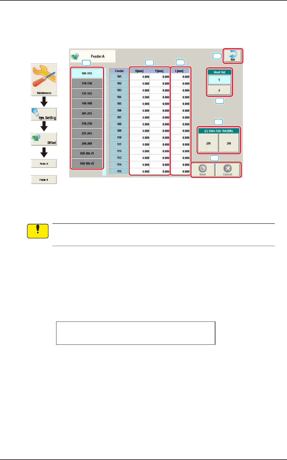
2.3 Feeder A / Feeder B
Pressing the [Feeder A] or [Feeder B] button on the "Offset Data" window displays the following
window.
or
Graphic
Development
[1]
[2]
[3]
[4]
[5]
[6]
[7]
F3B23A
Feeder Offset A
This offset data is used to correct variation in each feeder slot (Fdr No.) of the feeder base.
The parameters measured at shipment of the machine are entered.
Do not change the parameters unless necessary.
Feeder Offset B
This offset data is used to correct variation in the feeder.
• The X and Y parameters are recognition-processed during the automatic operation to track the
positional relation between the nozzle and component centers and updated automatically for
better pickup posture (pickup on the component center).
Note: In normal cases, it is not necessary to enter any parameters.
• The "L [mm]" parameters are not updated automatically but the entered ones are reflected.
Feeder offset parameters are added to actual offset values.
Actual Offset Values = Feeder (A) Offset + Feeder (B) Offset
[1] Feeder Change Tab
Another tab sheet can be opened by pressing the corresponding "Feeder Base" tab.
Notice