EUKYX-199-3100_G5S2_Instruction_Vol3_E.pdf - 第156页
EUKYX 2-8 199-3100 2.1 Device Offset 2. 1 .6 T each Plate Pressi ng the [T each Pl ate ] tab on the "D evi ce Of fset " window d isp la ys the fol low in g win dow . Graphic Development F3B1 1A [ 1 ] He ad 1 / …
EUKYX
2-7199-3100
2.1 Device Offset
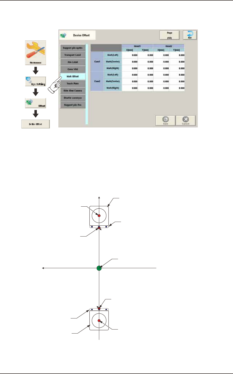
2.1.5 Mark Offset
Pressing the [Mark Offset] tab on the "Device Offset" window displays the following window.
Graphic
Development
F3B9A
"Mark (Center)" represents the standard mark position captured by the PEC recognition camera
when the rotational center of the head is moved to the area above the component recognition
camera.
"Mark (Right)" and "Mark (Left)" are the standard mark positions captured by the PEC recognition
camera when the pertinent nozzle is moved to the center of the component recognition camera
with the head being rotated 90° or 270°.
Xm(+)
Ym(+)
Component Recognition
Camera
Head Rotational Center
Standard Mark
Center of PEC Recognition
Camera
Pm. Machine Reference
Coordinate Origin
Standard Mark
Center of PEC Recognition
Camera
Component Recognition
Camera
Head Rotational Center
F3B10
EUKYX
2-8199-3100
2.1 Device Offset
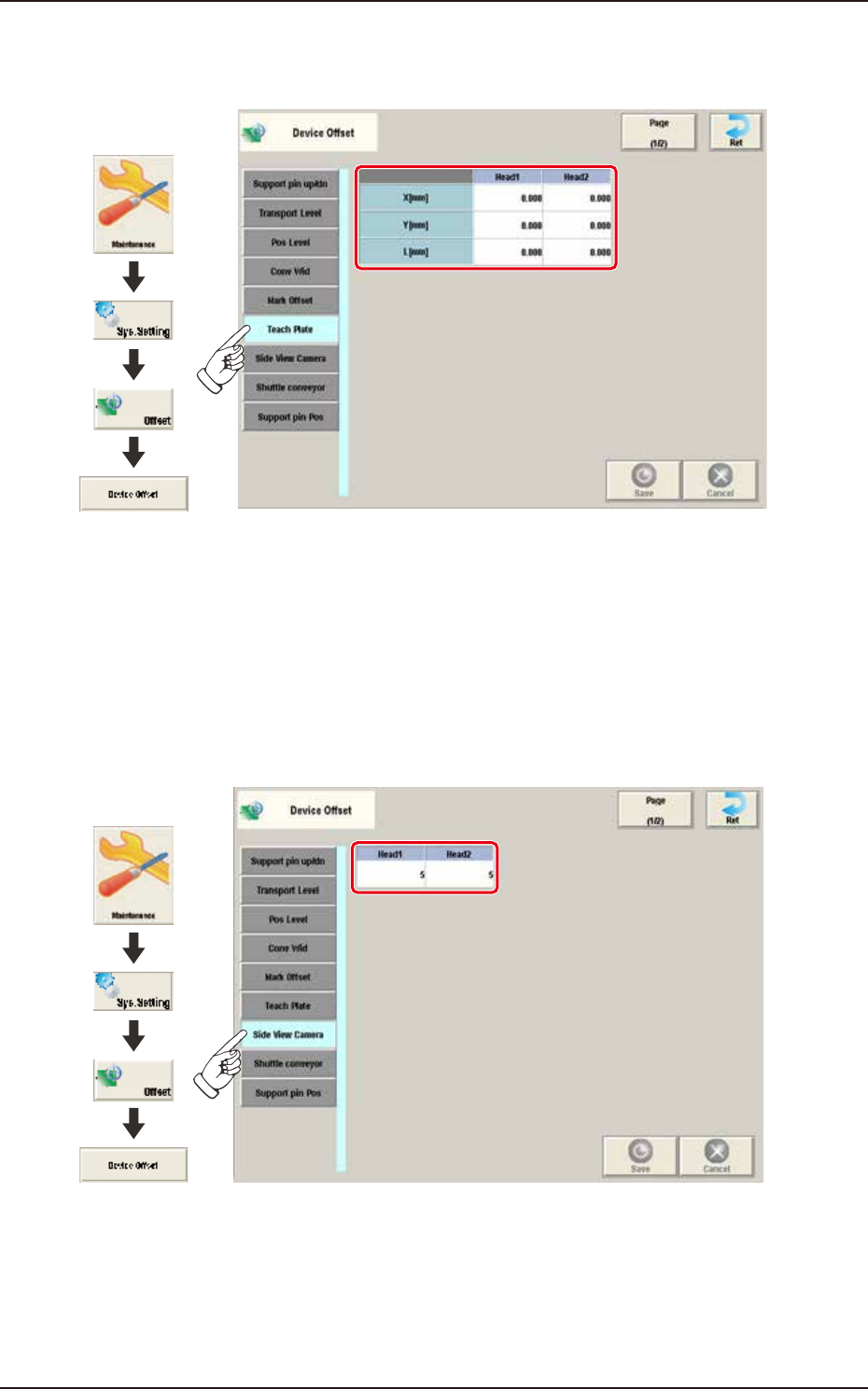
2.1.6 Teach Plate
Pressing the [Teach Plate] tab on the "Device Offset" window displays the following window.
Graphic
Development
F3B11A
[1] Head 1 / Head 2
X (Horizontal), Y (Vertical), and L (Height) [mm]
Enter the parameters required to adjust the deviations based on the design position of the jig
depot.
2.1.7 Side View Camera
Pressing the [Side View Camera] tab on the “Device Offset” window displays the following window.
Graphic
Development
F3B12A
Head 1 / Head 2
Set the number of dirt detection scanning times to be conducted by the side view camera of each
head.
EUKYX
2-9199-3100
2.1 Device Offset
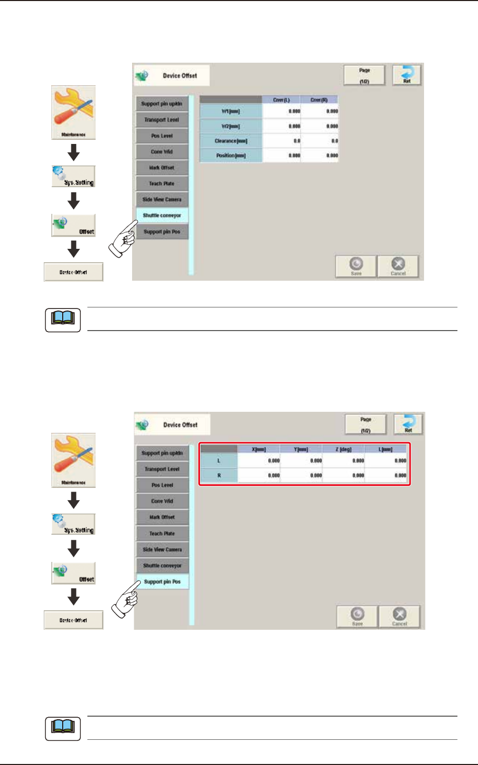
2.1.8 Shuttle conveyor
Pressing the [Shuttle conveyor] tab on the "Device Offset" window displays the following window.
Graphic
Development
F3B13A
This setting is used as an option.
2.1.9 Support pin Pos
Pressing the [Support pin Pos] tab on the “Device Offset” window displays the following window.
Graphic
Development
F3B14A
[1] L / R
X [mm], Y [mm], Z [deg], L [mm]
These offset parameters are to be corrected when the support pin data is converted. These offset
parameters are calculated automatically in the support pin teaching operation.
When this teaching is performed, the dedicated teaching pins are required.
Note
Note