EUKYX-199-3100_G5S2_Instruction_Vol3_E.pdf - 第174页
EUKYX 2-26 199-3100 2.5 Head 2.5.4 Each A ng. Lead Pressi ng the [Each Ang. L ead] ta b on the "Head" windo w dis pl a ys the fol lowi ng wi nd ow . [1] [2] [3] [4] Graphic Development F3B35A [ 1 ] Nozzl e 1 th…
EUKYX
2-25199-3100
2.5 Head
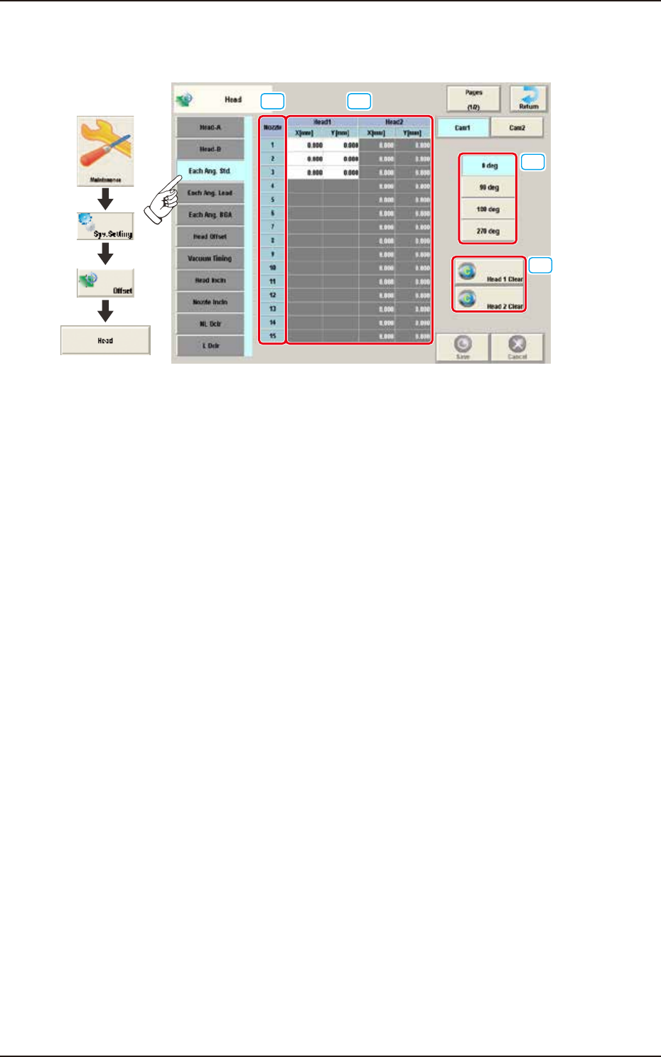
2.5.3 Each Ang. Std
Pressing the [Each Ang. Std] tab on the "Head" window displays the following window.
[1] [2]
[3]
[4]
Graphic
Development
F3B34A
[1] Nozzle 1 through 15
In this section, each nozzle No. is displayed.
[2] Head 1 and Head 2
X (Horizontal) and Y (Vertical) [mm]
When the applicable component is a each angle one, conversion and addition are made in response
to the placement angle while the target position for placement is being computed.
[3] Head Direction Selection Buttons
When this button is selected, the head direction is adjusted for each selected angle.
[4] [Head 1 Clear] Button, [Head 2 Clear] Button
Using these buttons, the data parameters for all the nozzles in the corresponding head are
performed.
EUKYX
2-26199-3100
2.5 Head
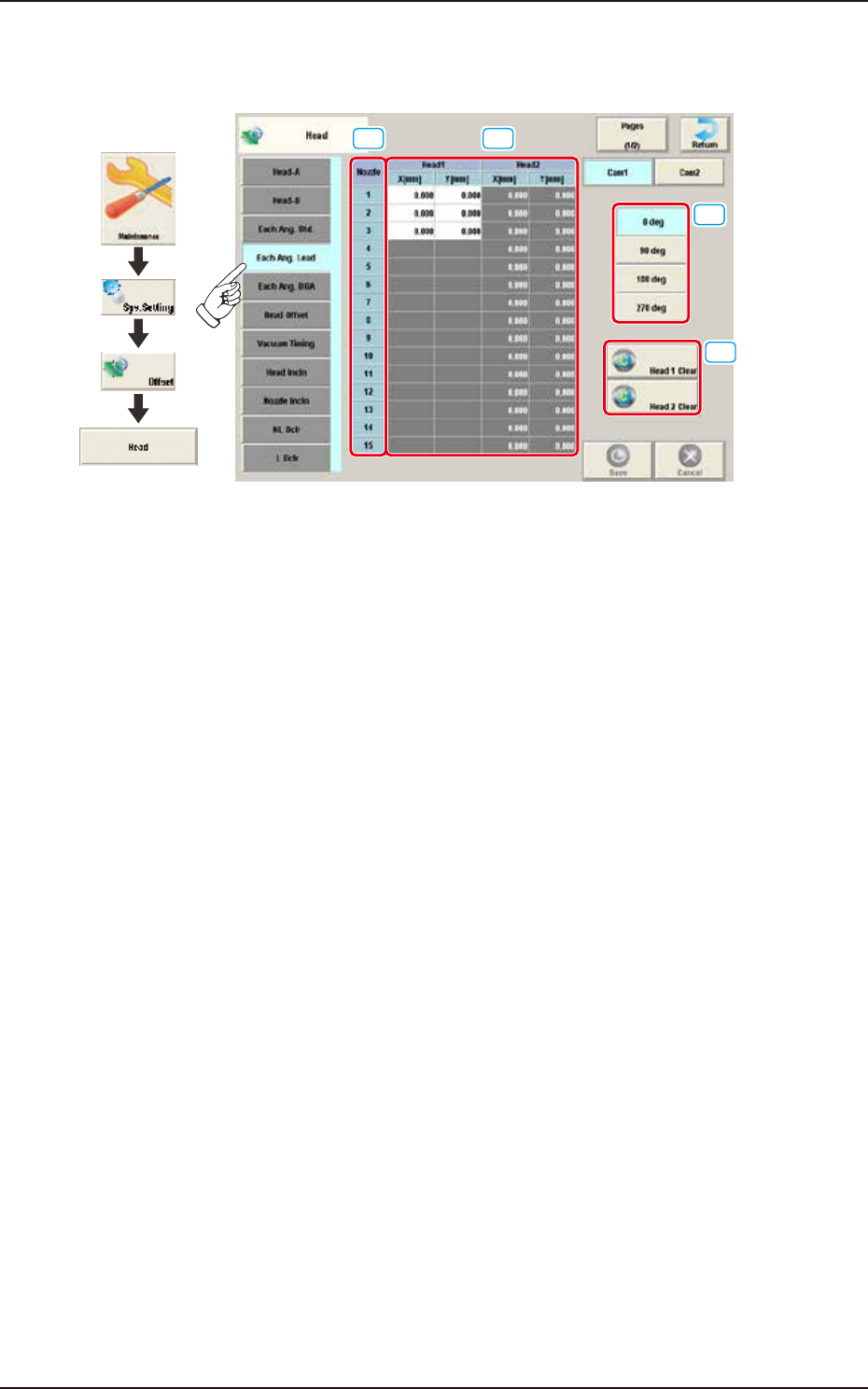
2.5.4 Each Ang. Lead
Pressing the [Each Ang. Lead] tab on the "Head" window displays the following window.
[1] [2]
[3]
[4]
Graphic
Development
F3B35A
[1] Nozzle 1 through 15
In this section, each nozzle No. is displayed.
[2] Head 1 and Head 2
X (Horizontal) and Y (Vertical) [mm]
When the applicable component is a leaded one, conversion and addition are made in response to
the placement angle while the target position for placement is being computed.
[3] Head Direction Selection Buttons
When this button is selected, the head direction is adjusted for each selected angle.
[4] [Head 1 Clear] Button, [Head 2 Clear] Button
Using these buttons, the data parameters for all the nozzles in the corresponding head are
performed.
EUKYX
2-27199-3100
2.5 Head
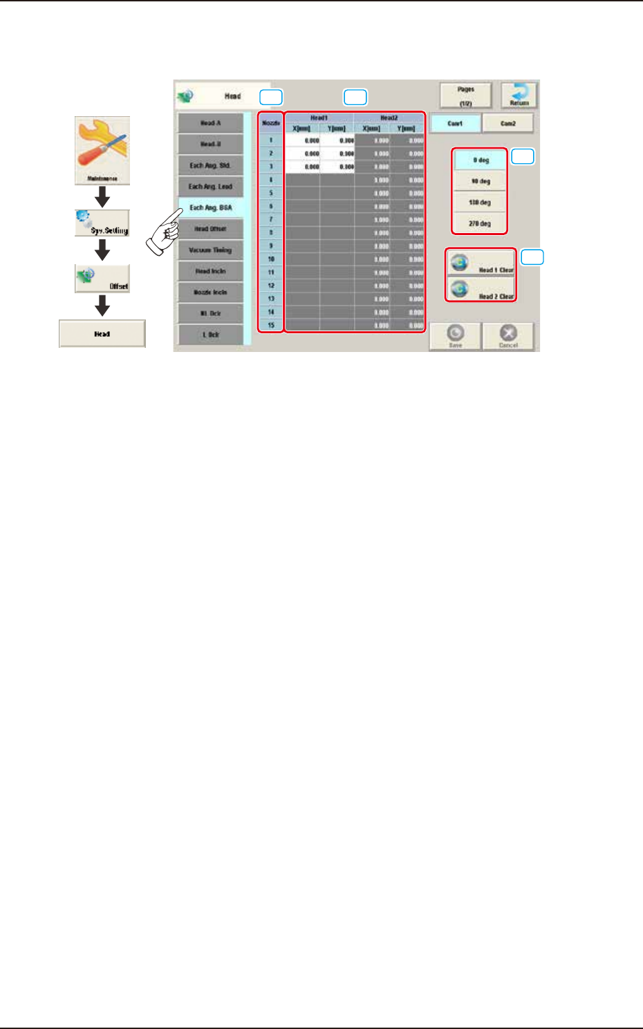
2.5.5 Each Ang. BGA
Pressing the [Each Ang. BGA] tab on the "Head" window displays the following window.
[1] [2]
[3]
[4]
Graphic
Development
F3B36A
[1] Nozzle 1 through 15
In this section, each nozzle No. is displayed.
[2] Head 1 and Head 2
X (Horizontal) and Y (Vertical) [mm]
When the applicable component is a BGA/CSP one, conversion and addition are made in response
to the placement angle while the target position for placement is being computed.
[3] Head Direction Selection Buttons
When this button is selected, the head direction is adjusted for each selected angle.
[4] [Head 1 Clear] Button, [Head 2 Clear] Button
Using these buttons, the data parameters for all the nozzles in the corresponding head are
performed.