EUKYX-199-3100_G5S2_Instruction_Vol3_E.pdf - 第89页
EUKYX 1-40 199-3100 5.9 Cmp Recog Pos 5.9 Cmp Recog P os Thi s wi ndow per forms a teac hi ng operation on the component recogni tion camera offset s (X ( mm) Horiz ontal , Y ( mm) V er tical , and Z ( deg ) Angl e) . [1…

EUKYX
1-39199-3100
5.8 PCB Recog/Beam
• Glass jig board JG-0166 (PEC Recognition Calibration Jig)
For the "PEC Recognition Camera & Beam Offset" teaching, the following glass jig board is used.
Before the teaching operation, position and clamp the glass jig board on the PCB positioning center.
• Teaching Procedure
(1) Select the Beam (1 or 2) for which the teaching is performed.
(2) Press the [Use] button in the "Glass Jig" section.
(3) Press the [Teach Start] button. The designated beam (1 or 2) will move to the specified
recognition mark position and the following teaching operation will be performed.
• PEC Recognition Camera Magnification X (Horizontal), Y (Vertical), Z (Angle) Teaching
(Camera 1 or 2)
• Beam X (Horizontal) and Y (Vertical) Offset Teaching (Beam 1 or 2)
• Beam Angle Z, Angle Y, Rectangular X Offset Teaching (Beam 1 or 2)
• Pilot Pin Bending Position X Side, Angle (Beams 1 and 2)
• When any recognition error occurs during the teaching or the [STOP] button is pressed
on the operation panel, the machine is stopped temporarily. In this case, re-start is available.
• During this temporary stop mode, the selection of any other menu item is unavailable.
When the teaching is completed, the designated head returns to the home position
automatically. The teaching results and mark recognition results during the teaching (XY
Angles) are displayed in the display area on the "PEC Recognition Camera & Beam
Offset" window.
(4) Press the [Save] button to save the teaching results.
Procedure
Note
EUKYX
1-40199-3100
5.9 Cmp Recog Pos
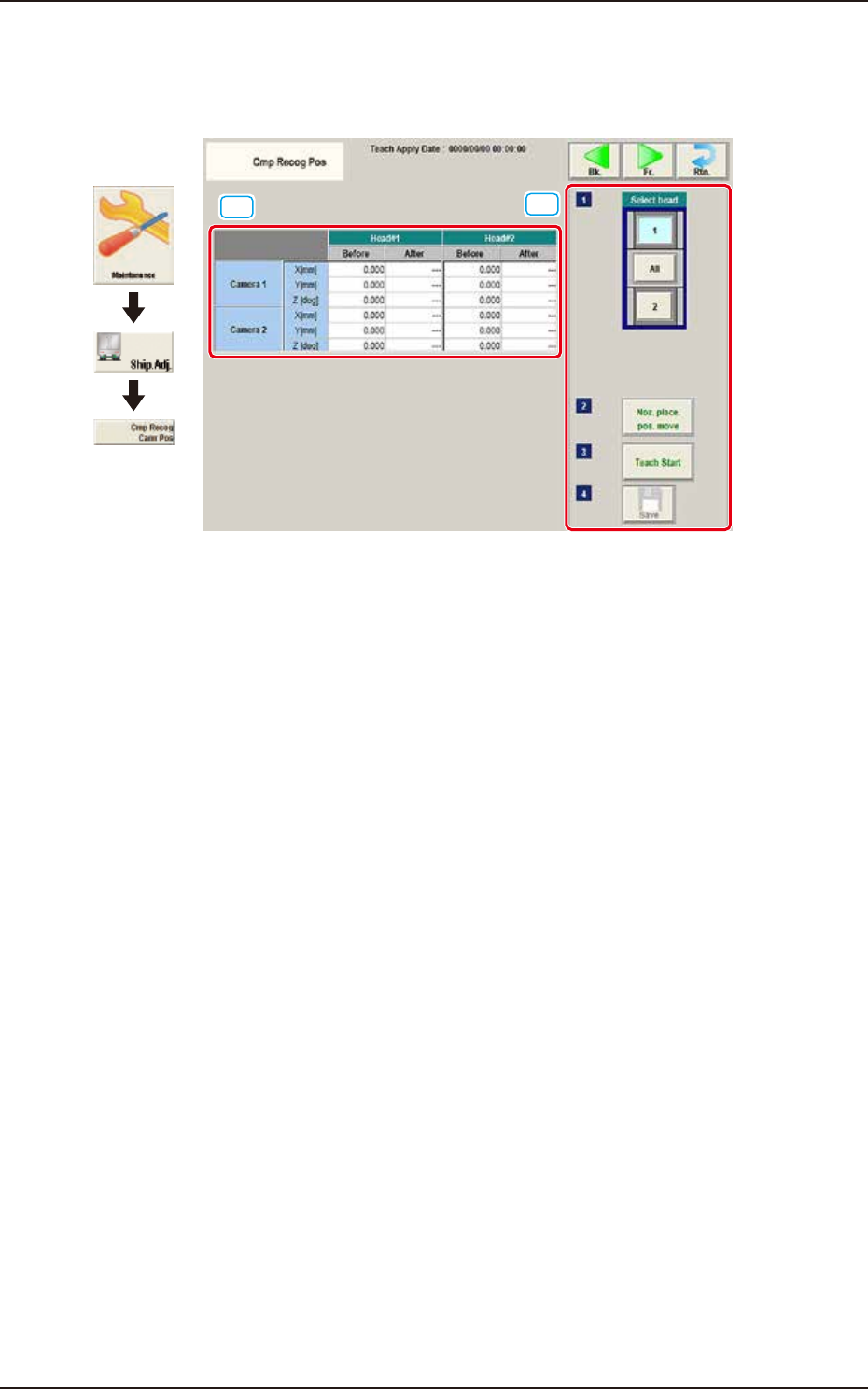
5.9 Cmp Recog Pos
This window performs a teaching operation on the component recognition camera offsets (X (mm)
Horizontal, Y (mm) Vertical, and Z (deg) Angle).
[1]
[2]
Graphic
Development
F3A36
[1] Teaching Data Display Section
Displayed are the each offset data items for the designated camera and head.
[2] Teaching procedures section
The following buttons are arranged in teaching procedures section.
Select head
Selects the head whose component recognition camera is taught.
[Noz. Place. Pos. move] Button
The head is moved to the position where the nozzle to be used for the teaching can be
attached easily.
[Teach Start] button
Starts the teaching.
[Save] button
The teaching results are saved.
EUKYX
1-41199-3100
5.9 Cmp Recog Pos
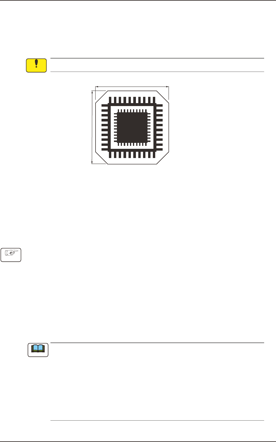
• Component Recognition Camera Offset Teaching Jig
For the component recognition camera offset teaching, the following jig is used.
Before the teaching operation, place the jig at its setup position and when the teaching is
completed, remove it.
QFP Glass Jig JG-0188 (KYB-M381P-00, Standard Equipment)
This jig is fragile, so take the greatest care to handle it.
12 mm
12 mm
On the glass, the two patterns for the positional calculation are vapor-deposited.
F3A37
• Jig Pick-up Nozzle
For the pick-up of the QFP glass jig, the jig nozzle (standard equipment) or the normal vacuum
nozzle HV19C is used.
Before the teaching operation, change the nozzle in the "NOZ.CHNG." window (Operation
Sequence: Select [Unit Adj.] button in the Menus for Maintenance
→
Select [Noz Chng.] button).
• Component Recognition Camera Offset Teaching Procedure
(1) Before the teaching operation, place the QFP glass jig at its setup position with the vapor-
deposited surface turned down.
(2) Press the [Noz. Place. Pos. move] button. (Move the head to the position where the nozzle
to be used for teaching can be attached easily.)
(3) Press the [Teach Start] button. (The component recognition camera offset (X (Horizontal), Y
(Vertical) and Z (Angle)) teaching will be executed.)
• The beam selected in the position setting operation is move to the jig setup position and the
glass jig is recognized using the PEC recognition camera.
After that, the jig in the jig setup position is picked up and moved to the position above the
component recognition camera. The nozzle is lowered to the focus point of the jig and the
recognition is performed. Then, the camera offset is calculated.
•
When any recognition error occurs during the teaching operation or the
[STOP] button is pressed on the operation penal, the machine is stopped
temporarily. In this case, re-start is available.
•
During this temporary stop mode, the selection of any other menu item is unavailable.
When the offset teaching is completed, the jig is returned to the specified jib setup
position and the designated head returns to the home position automatically.
The teaching results and mark recognition results during the teaching (XY Angles) are
displayed in the “X (Horizontal) (mm)”, “Y (Vertical) (mm)”, and “Angle Z (
°
)” data boxes
in the “PEC Recognition Camera & Beam Offset” window.
(4) Press the [Save] button. (The teaching results are saved.)
Notice
Procedure
Note