EUKYX-199-3100_G5S2_Instruction_Vol3_E.pdf - 第160页
EUKYX 2-12 199-3100 2.1 Device Offset 2 .1.12 M a r k - C h e c k Pressi ng the [Mark-Check] tab on the "Device Of fset " window d isp la ys the fol low in g wi ndow . [1] [2] Graphic Development F3B17A [1] M a…
EUKYX
2-11199-3100
2.1 Device Offset
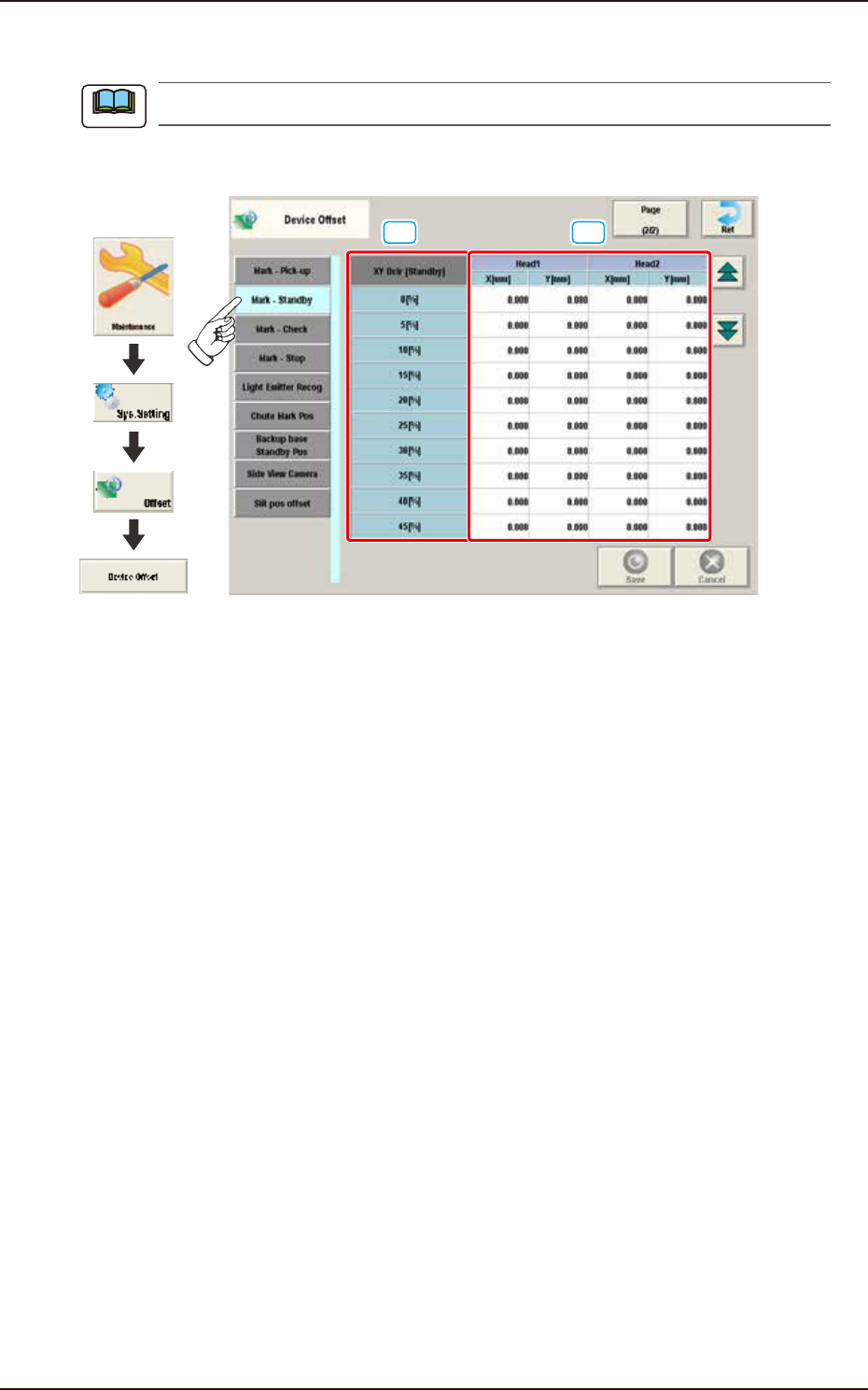
2.1.11 Mark-Standby
This window is not displayed when the multi-functional head is selected.
Pressing the [Mark-Standby] tab on the "Device Offset" window displays the following window.
[1] [2]
Graphic
Development
F3B16A
[1] XY Dclr [Standby]
0 [%] to 45 [%]
The XY speed reduction rate is displayed in these data boxes.
[2] Head 1, 2
X [mm], Y [mm]
The deviation for the head X, Y when the head is moved from the reference mark to the waiting
position, is corrected based on the XY speed reduction rate.
Note
EUKYX
2-12199-3100
2.1 Device Offset
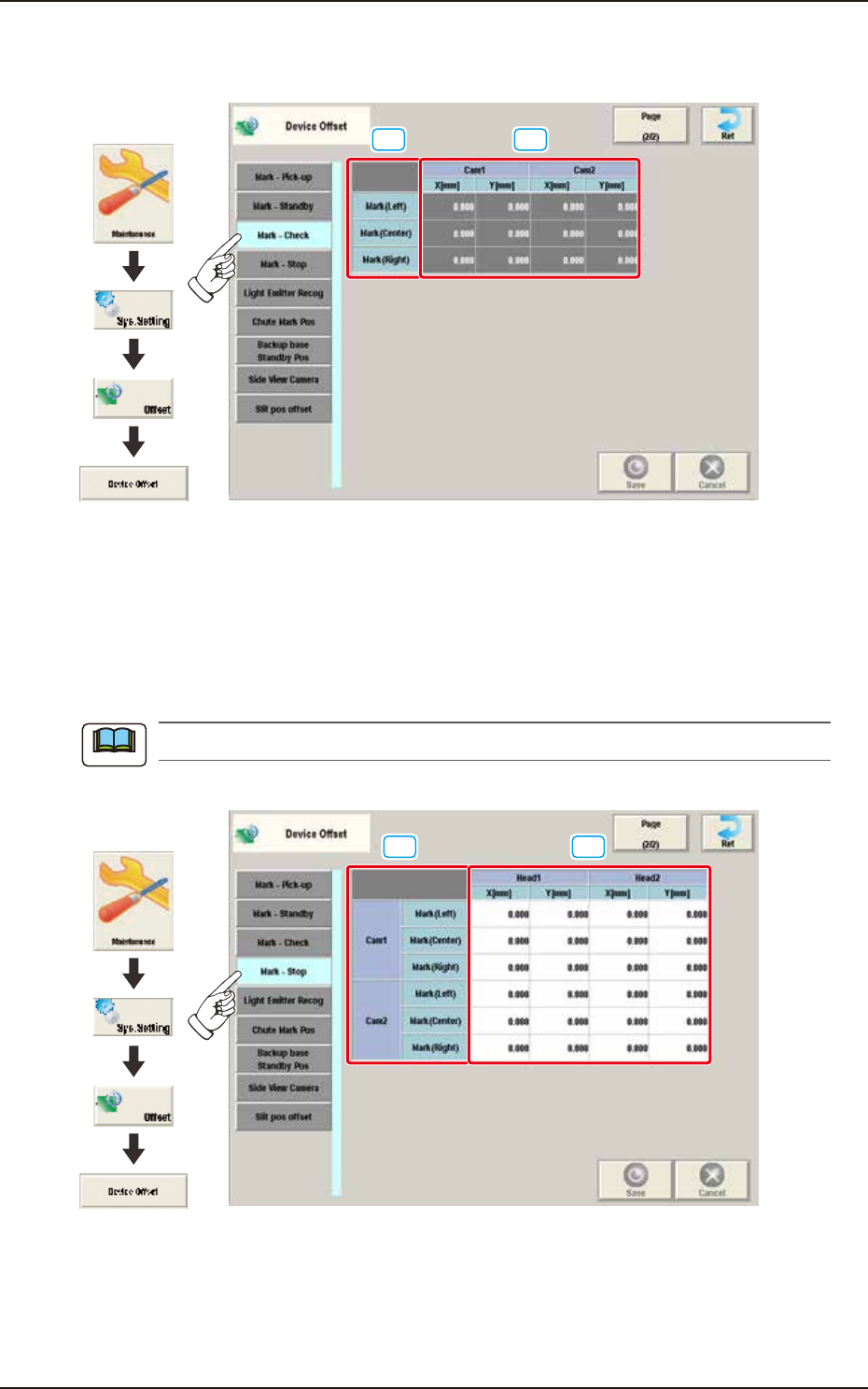
2.1.12 Mark-Check
Pressing the [Mark-Check] tab on the "Device Offset" window displays the following window.
[1] [2]
Graphic
Development
F3B17A
[1] Mark
The Reference Mark position is displayed in these data boxes.
[2] Cam 1 / 2
X [mm] / Y [mm]
The deviation for the camera XY position in the reference mark check operation, is adjusted.
2.1.13 Mark-Stop
This window is not displayed when the multi-functional head is selected.
Pressing the [Mark-Stop] tab on the “Device Offset” window displays the following window.
[1] [2]
Graphic
Development
F3B18A
[1] Cam 1 / 2
The marks from each camera are displayed.
[2] Head 1 / 2
X [mm] / Y [mm]
The reference mark (stop check) offset based on the camera and each mark, is adjusted.
Note
EUKYX
2-13199-3100
2.1 Device Offset
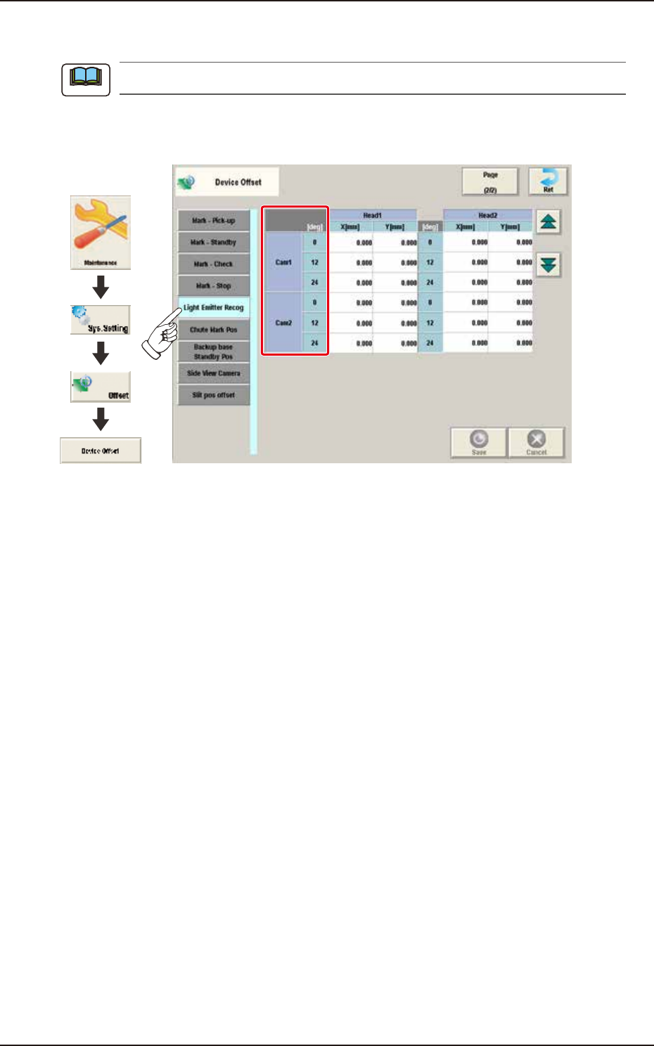
2.1.14 Light Emitter Recog
This window is not displayed when the multi-functional head is selected.
Pressing the [Light Emitter Recog] tab on the "Device Offset" window displays the following
window.
Graphic
Development
F3B19A
Cam 1 / 2
The offsets for the Heads 1 and 2 based on each camera position, are displayed in the units of 12
degrees".
Note