EUKYX-199-3100_G5S2_Instruction_Vol3_E.pdf - 第189页
EUKYX 2-41 199-3100 2.6 Nozzle 2.6.5 L S Detection Pressi ng the [L S Detec tion] tab on the "Nozzl e" win dow di spl a ys the fol lowi ng wi ndow . [1] [2] Graphic Development F3B52A [1] N o z z l e In thi s s…
EUKYX
2-40199-3100
2.6 Nozzle
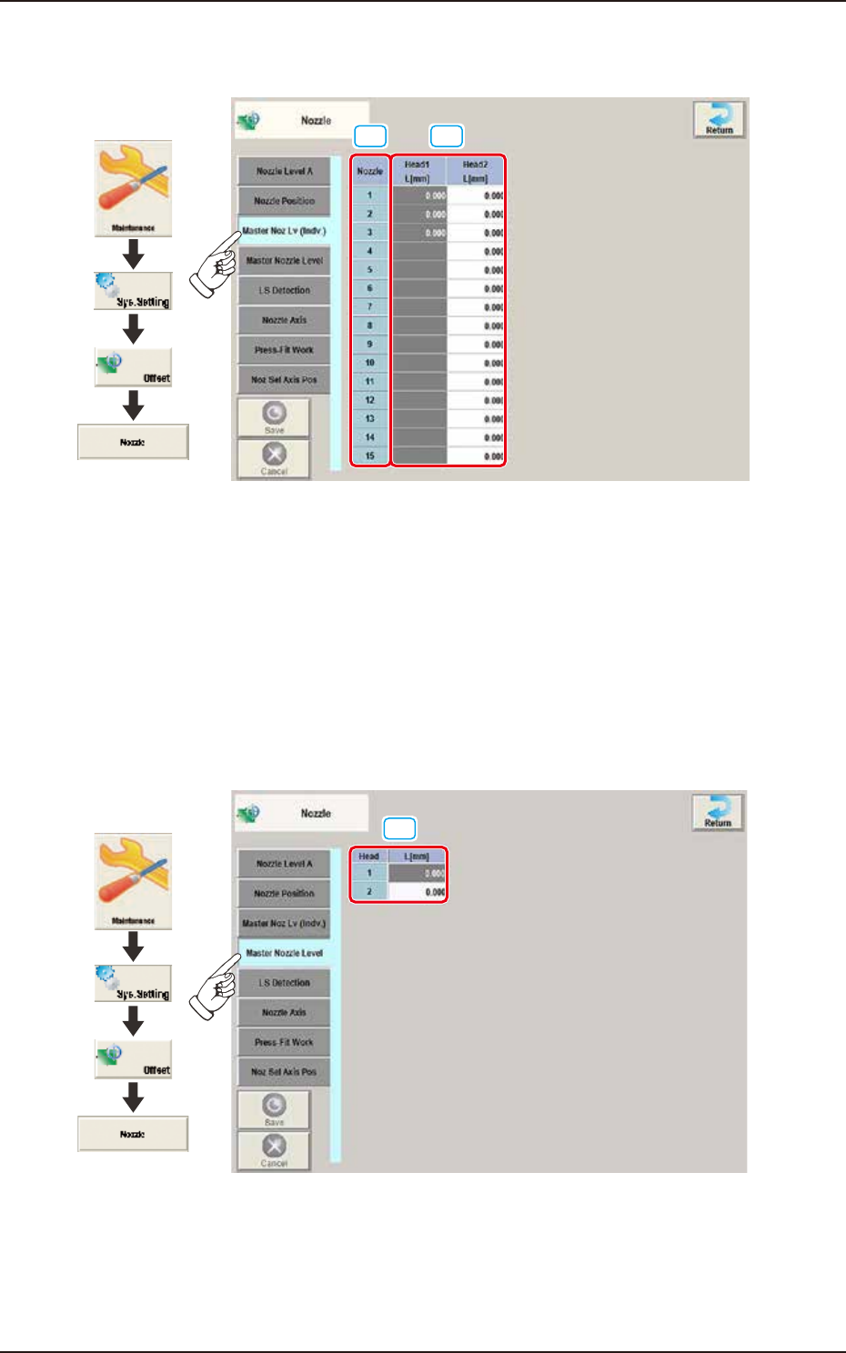
2.6.3 Master Noz Lv (Indv.)
Pressing the [Master Noz Lv (Indv.)] tab on the "Nozzle" window displays the following window.
[1] [2]
Graphic
Development
F3B50A
[1] Nozzle
In this section, each nozzle No. is displayed.
[2] Head 1 / Head 2
L [mm]
Each parameter indicates the reference position (the values read by the side view camera) of the
master nozzle bottom level.
Save the values of the master nozzle bottom level that was read by the side view camera and used
when the head up/down offsets were obtained with the nozzle U/D axes being zeroed.
2.6.4 Master Nozzle Level
Pressing the [Master Nozzle Level ] tab on the “Nozzle” window displays the following window.
[1]
Graphic
Development
F3B51A
[1] Head 1 / Head 2
L [mm]
Each parameter indicates the reference position (the values read by the side view camera) of the
master nozzle bottom level.
Save the values of the master nozzle bottom level that was read by the side view camera and used
when the head up/down offsets were obtained with the nozzle U/D axes being zeroed.
EUKYX
2-41199-3100
2.6 Nozzle
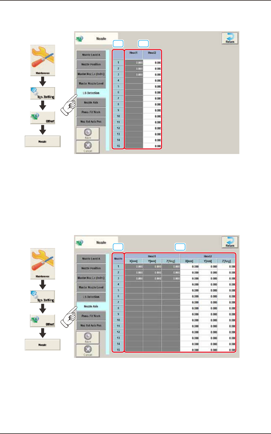
2.6.5 LS Detection
Pressing the [LS Detection] tab on the "Nozzle" window displays the following window.
[1] [2]
Graphic
Development
F3B52A
[1] Nozzle
In this section, each nozzle No. is displayed.
[2] Head 1 / Head 2
Z [Ang]
As these parameters are for dummy PCB, they are not used currently.
2.6.6 Nozzle Axis
Pressing the [Nozzle Axis] tab on the “Nozzle” window displays the following window.
[1] [2]
Graphic
Development
F3B53A
[1] Nozzle
In this section, each nozzle No. is displayed.
[2] Head 1 / Head 2
X (Horizontal) / Y (Vertical) [mm] / Z [Ang]
Displayed is the offset data for nozzle replacement.
The displayed values indicate the offsets for the lowest levels of the special nozzles on the heads.
The lowest level of each nozzle is measured by the component recognition camera and the
difference between the actual and recognized levels is compensated for.
EUKYX
2-42199-3100
2.6 Nozzle
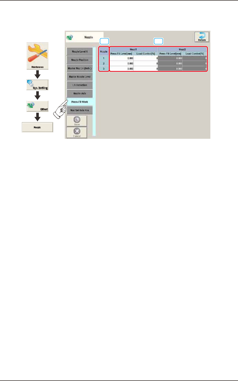
2.6.7 Press-Fit Work
Pressing the [Press-Fit Work] tab on the "Nozzle" window displays the following window.
[1]
[2]
Graphic
Development
F3B54A
[1] Nozzle
In this section, each nozzle No. is displayed.
[2] Head 1 and Head 2
Press Fit Level [mm]
The correction is performed when the nozzle attachment position is deviated due to the
component change in these text boxes. Positive value reduces the operation range and
negative value increases the operation range.
Load Control [%]
It is the set load offset data for load limit.