EUKYX-199-3100_G5S2_Instruction_Vol3_E.pdf - 第54页
EUKYX 1-5 199-3100 3.1 Head Unit 3. 1 He ad Unit When the head un it button is pressed, the fol lowin g wi ndow appears. [1] Head unit button Graphic Development F3A6A [ 1 ] Unit sele ct [High V 1 2] But ton : When pres …
EUKYX
1-4199-3100
3. Unit Change
3. Unit Change
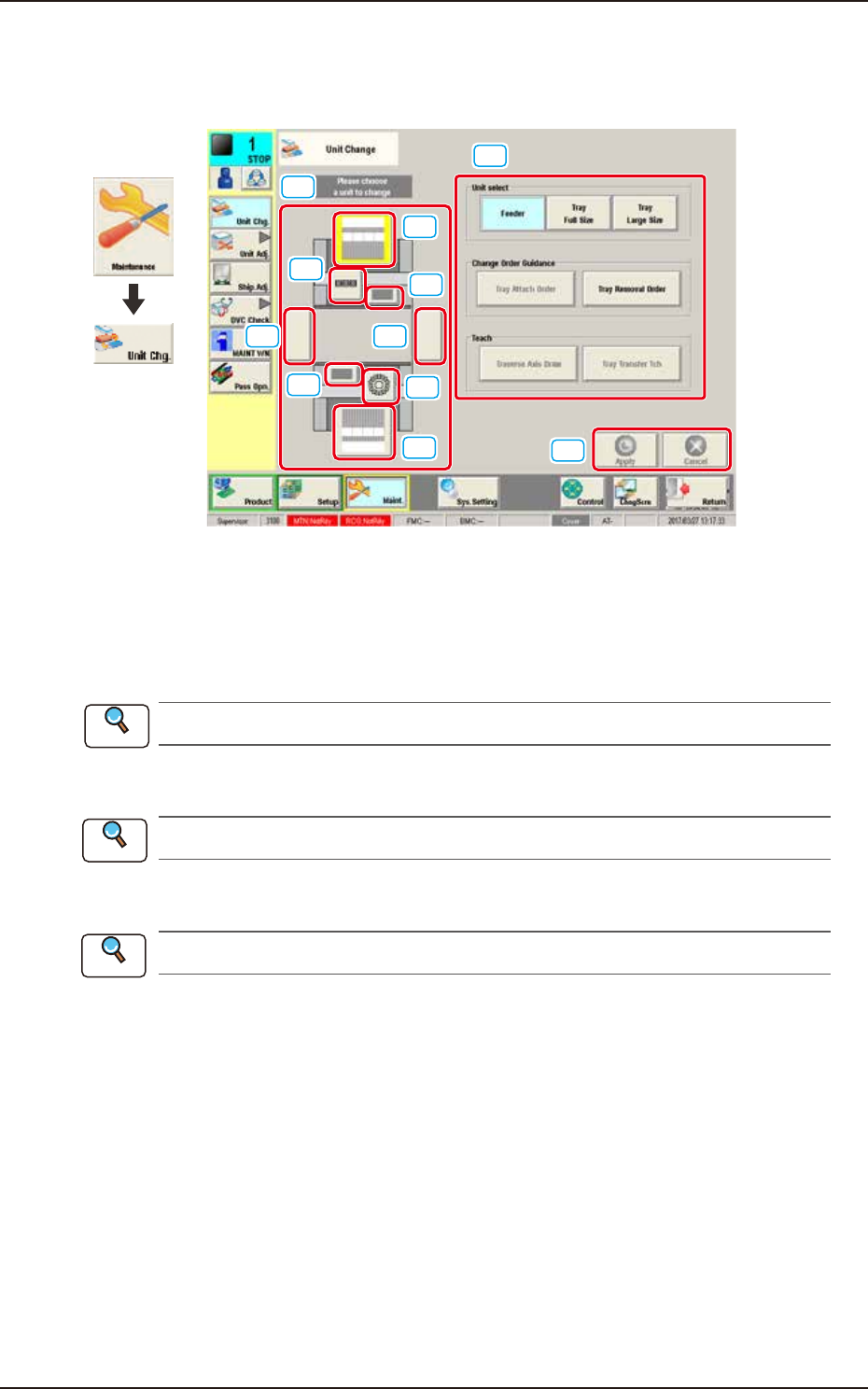
This window enables the operator to perform the unit change in the system.
[1]
[2]
[3]
[3]
[2]
[4]
[4]
[5][5]
[6]
[7]
Graphic
Development
F3A5A
[1] Unit Image Button
Shown are the image buttons for each unit and when the button for the unit to be changed is
pressed, the "Unit Operation Button" is changed.
[2] Head Unit Button
Refer to “3.1 Head Unit” in this chapter for the details.
[3] Nozzle Stocker Button
Refer to “3.2 Nozzle Stocker” in this chapter for the details.
[4] Feeder Unit Button
Refer to “3.3 Feeder Unit” in this chapter for the details.
[5] Conveyor Button
This button is optional.
[6] Unit Operation Button
The operation button for the unit selected using the unit image button, is displayed. The indication
is changed depending on the selected unit.
[7] [Apply] Button and [Cancel] Button
[Apply] Button : When pressed, this button applies the changed unit to the production line
configuration.
[Cancel] Button : When pressed, this button cancels the changed unit and returns it to the unit
before change.
Reference
Reference
Reference
EUKYX
1-5199-3100
3.1 Head Unit
3.1 Head Unit
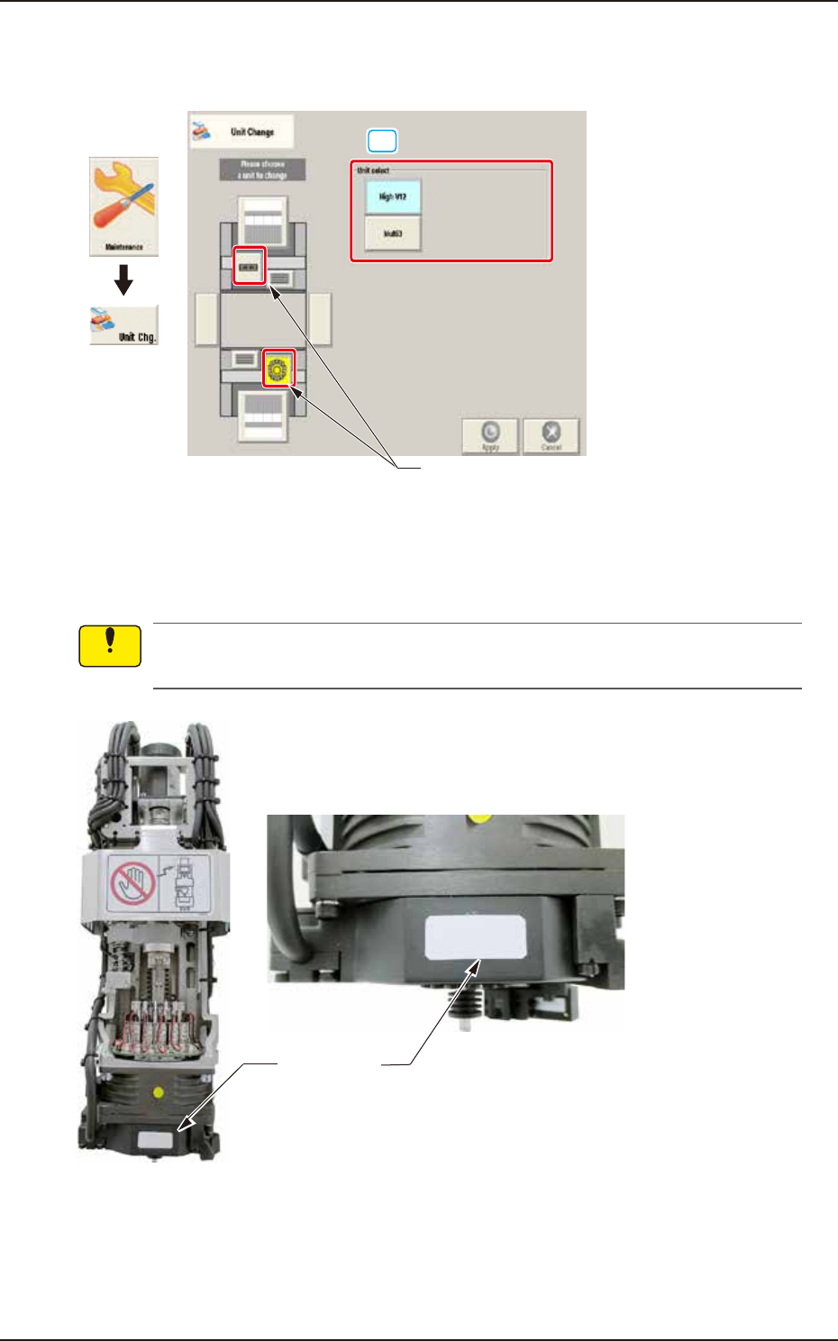
When the head unit button is pressed, the following window appears.
[1]
Head unit button
Graphic
Development
F3A6A
[1] Unit select
[High V12] Button : When pressed, the high-speed head is selected.
[Multi3] Button : When pressed, the multi-functional head is selected.
A white label is adhered to V12 head front. Make sure not to mount V10 head without label
when replacing head unit.
White label
Enlarged photo of head front
F3A6B
Notice
EUKYX
1-6199-3100
3.1 Head Unit
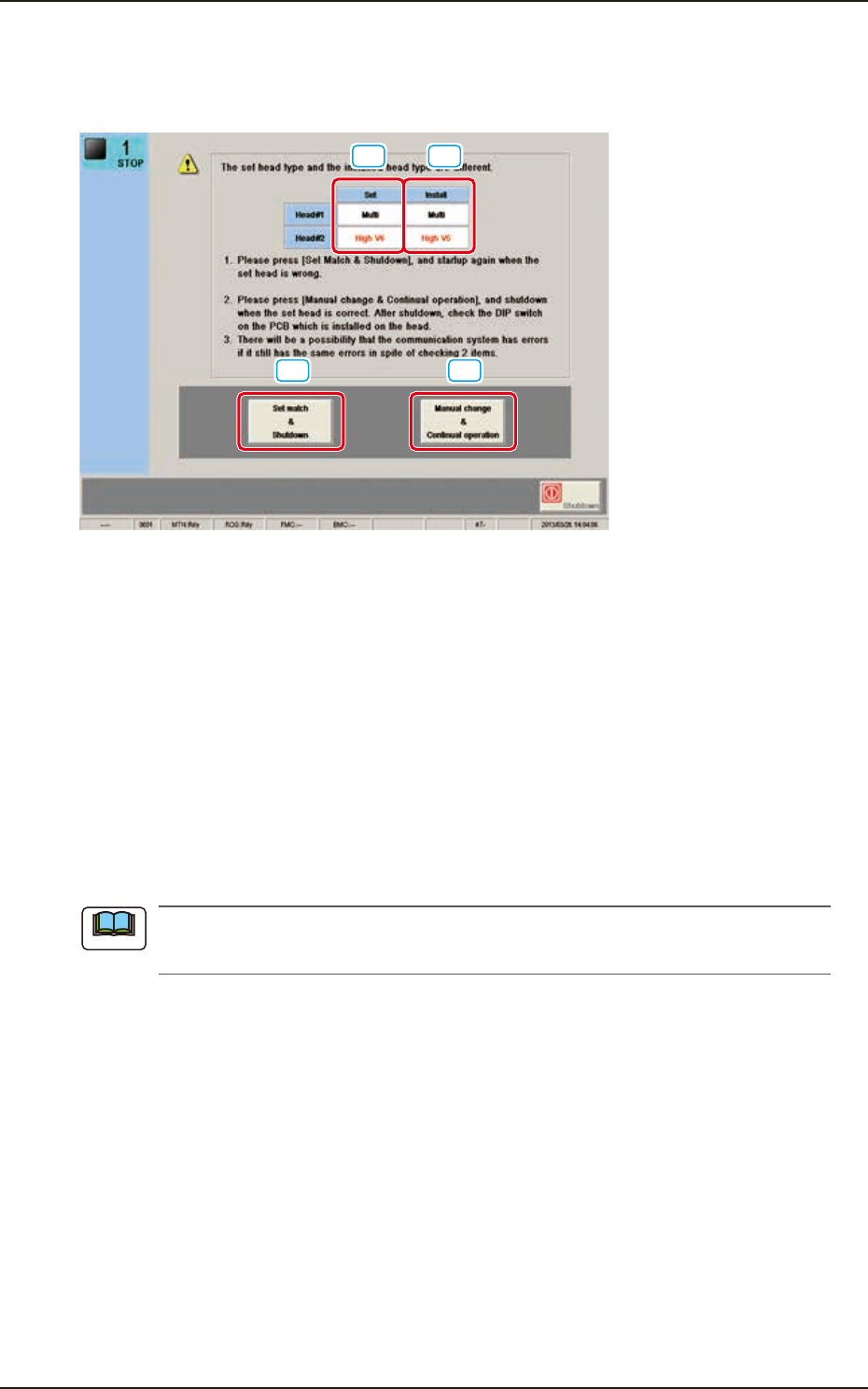
3.1.1 Attached Head Judgment Window
This window is displayed when the head option is not the same as one set as the head to be
attached when the machine is started up.
[1] [2]
[3] [4]
F3A7A
[1] Set
The head set in the machine is displayed in this data box.
In the case that the set head is "V12" head, "High-Speed V12" is displayed.
[2] Install
The head attached to the machine is displayed in this data box.
In the case that the attached head is "V12" head, "High-Speed V12" is displayed.
[3] [Set match & Shutdown] button
When the set head is not the same as the attached head, press this button to re-start the system.
[4] [Manual change & Continual operation] button
When the set head is the same as the attached head, press this button to shutdown the system.
Then, check the dip switch on the PCB mounted on the head.
If this error occurs again, even when the dip switch is checked, it might be caused by the
communication system error.
Note