EUKYX-199-3100_G5S2_Instruction_Vol3_E.pdf - 第61页
EUKYX 1-12 199-3100 4.1 NOZ. CHNG. 4. 1 NO Z . CHNG. The no zzle a t tachment a nd hous in g can be per formed manua l ly . [1] [2] [4] [5] [3] Graphic Development F3A14 [ 1 ] He ad Sel When a but ton is p ressed, the co…
EUKYX
1-11199-3100
4. Unit Adj.
4. Unit Adj.
Graphic
Development
F3A13A
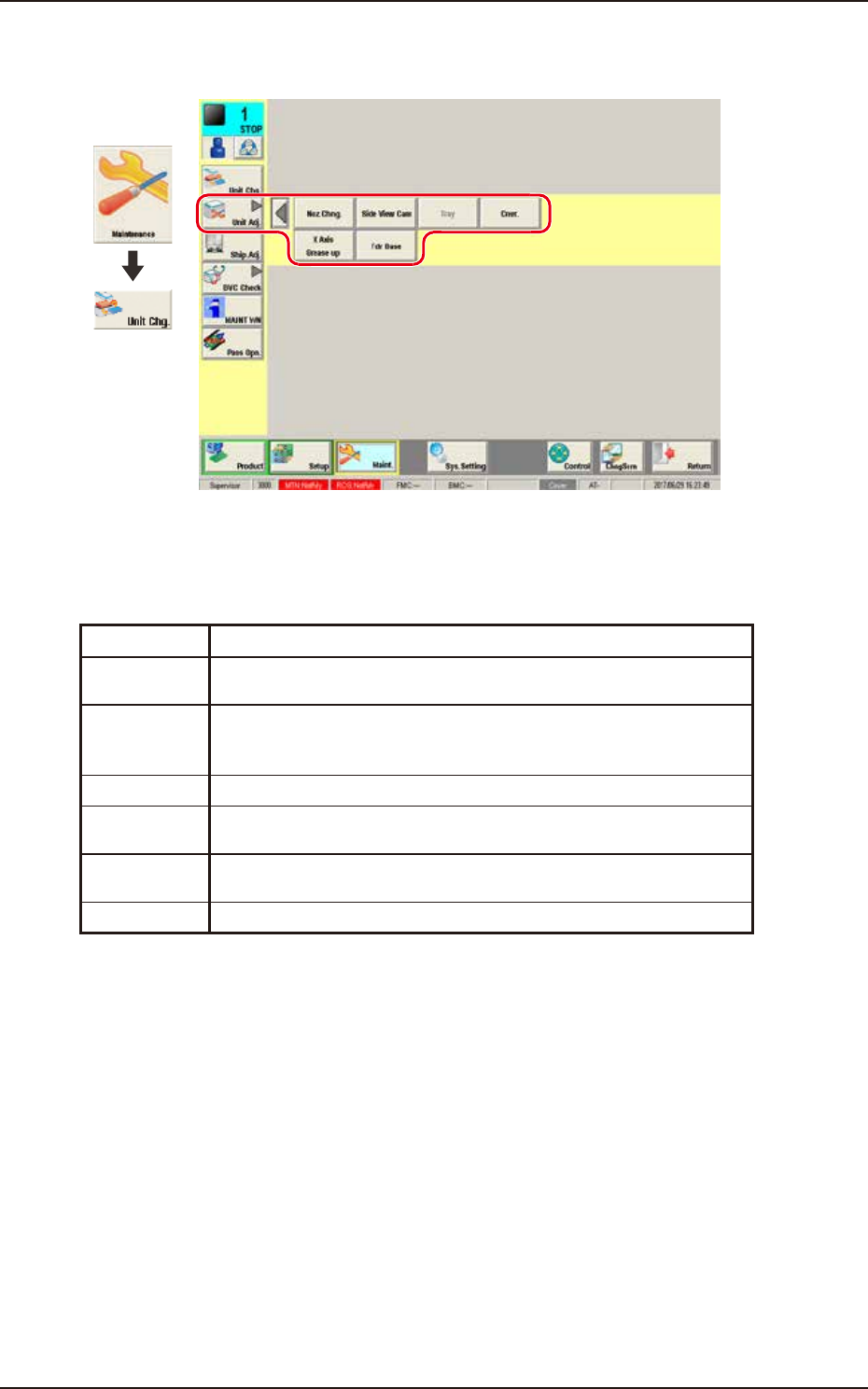
"Unit Adj." submenu
The following buttons are arranged on this submenu bar and can be used to display the operation
windows for execution of each unit adjustment function.
Button Description
Noz Chng. This button opens the "NOZ. CHNG." window to manually perform a
cycle of the vacuum nozzle attachment and storage operation.
Side View
Cam
This button performs the nozzle detection test with the side view camera
attached to each placement head to display the measurement value and
the measurement image.
Tray This button is used when the tray feeder (option) is adjusted.
Cnvr. This button is used to adjust the conveyor width overall setup or manual
setup.
X Axis
Grease up
This button is used when applying grease to the X-axis.
Fdr Base This button displays the connection status of the feeder base.
EUKYX
1-12199-3100
4.1 NOZ. CHNG.
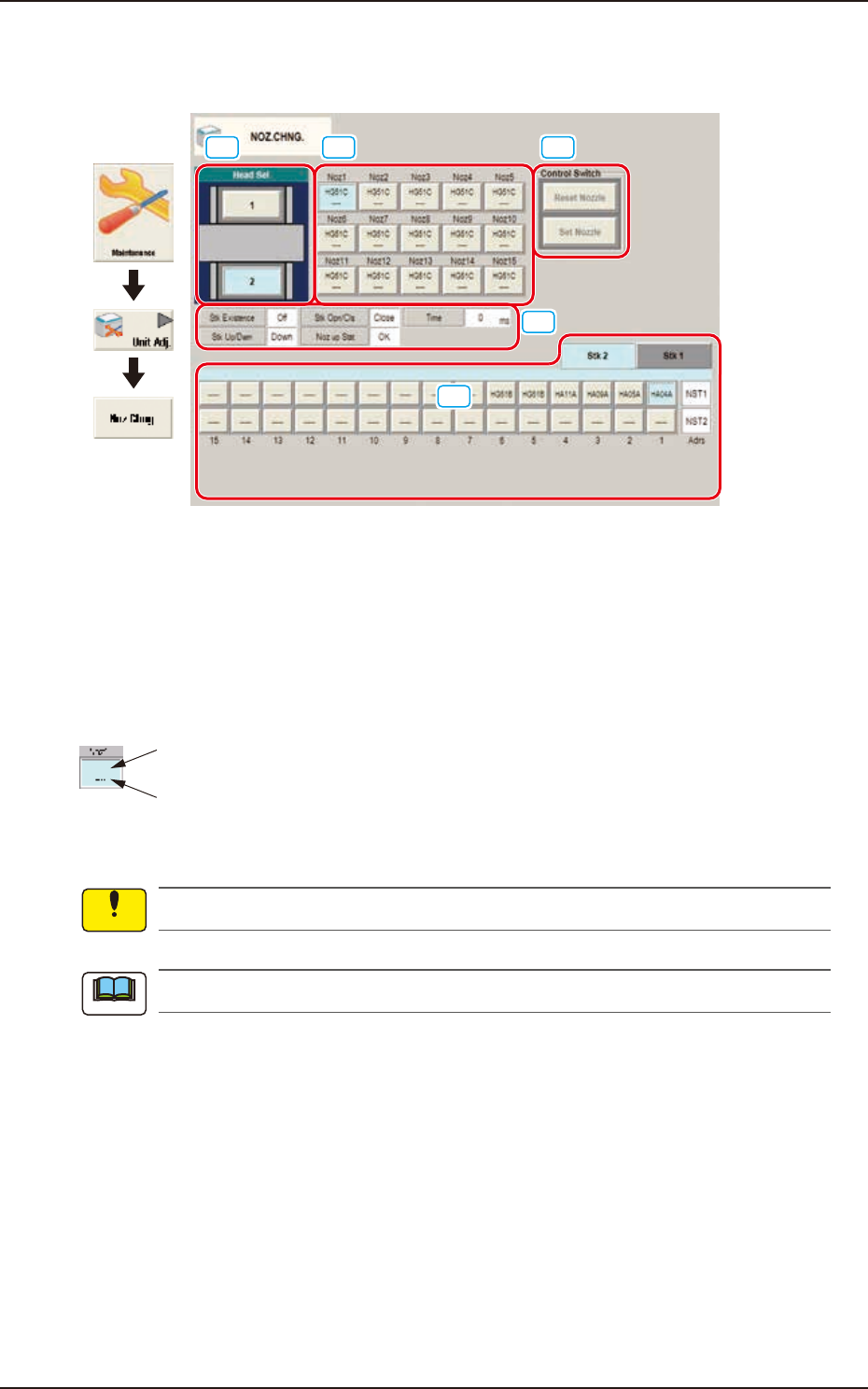
4.1 NOZ. CHNG.
The nozzle attachment and housing can be performed manually.
[1] [2] [4]
[5]
[3]
Graphic
Development
F3A14
[1] Head Sel
When a button is pressed, the corresponding head is selected as an object one for nozzle change
operation.
[2] Nozzle Allocation No. Selection Buttons
When a button is pressed, the corresponding nozzle to be changed is selected.
The background color of the button turns light blue.
ID of Attached Vacuum Nozzle
Nozzle Stocker Address
(Home Address for Attached Nozzle)
F3A18
No nozzles can be allocated to both sides of the middle-size odd shaped nozzle if attached.
The indications on the window vary depending on the selected head.
[3] Status Indication
Displayed is the condition of the currently selected head.
Notice
Note
EUKYX
1-13199-3100
4.1 NOZ. CHNG.
[4] "Control Switch" Group Box
The following operation buttons are arranged.
When the [START] button on the operation panel is pressed within 10 seconds after the each
operation button, the selected action takes place.
[Reset Nozzle] Button
When selected, this button stores the specified nozzle in the nozzle stocker.
When this button is pressed, the background color turns green, indicating that the head
selection button is set active.
[Set Nozzle] Button
When selected, this button picks up the selected nozzle from the nozzle stocker and
attaches it to the specified nozzle No. position.
When this button is pressed, the background color turns green, indicating that the head and
nozzle (nozzle stocker) selection buttons are set active.
[5] Nozzle Stocker tab
Using this tab, the nozzle stocker to be opened or closed and the nozzle housed in the nozzle
stocker, are designated.
Selecting the nozzle stocker using the nozzle stocker select tab and pressing the button for an
appropriate nozzle, designates the nozzle to be used.
For the stocker for which the skip has been set, a message is displayed and the stocker can not
be operated.
Note