EUKYX-199-3100_G5S2_Instruction_Vol3_E.pdf - 第200页
EUKYX 2-52 199-3100 2.9 Comp. Recog 2.9.4 Fly Recog X Y Pressi ng the [Fly R ecog X Y] t ab on the "Comp. Recog" wi nd ow di spla ys t he fol lowi ng window . Graphic Development F3B67 [ 1 ] He ad 1 / Hea d 2 X…
EUKYX
2-51199-3100
2.9 Comp. Recog
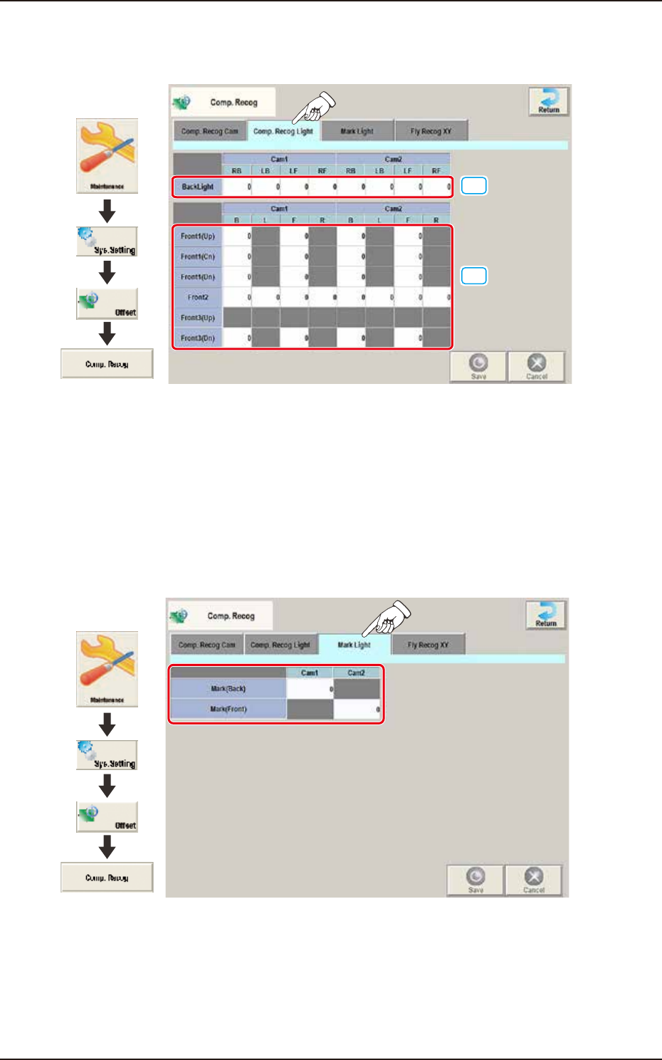
2.9.2 Comp. Recog Light
Pressing the [Comp. Recog Light] tab on the "Comp. Recog" window displays the following window.
[1]
[2]
Graphic
Development
F3B65
[1] Back Light
Set the light level for Comp. Recog Light.
[2] Front 1 (Up) / (Cn) / (Dn) / Front 2 / Front 3 (Up) / Front 3 (Dn)
Set the light level for Comp. Recog Light.
2.9.3 Mark Light
Pressing the [Mark Light] tab on the “Comp. Recog” window displays the following window.
Graphic
Development
F3B66
Mark (Back) / Mark (Front)
Cam1 / Cam2
The brightness level for the reference mark lighting is set in these text boxes.
EUKYX
2-52199-3100
2.9 Comp. Recog
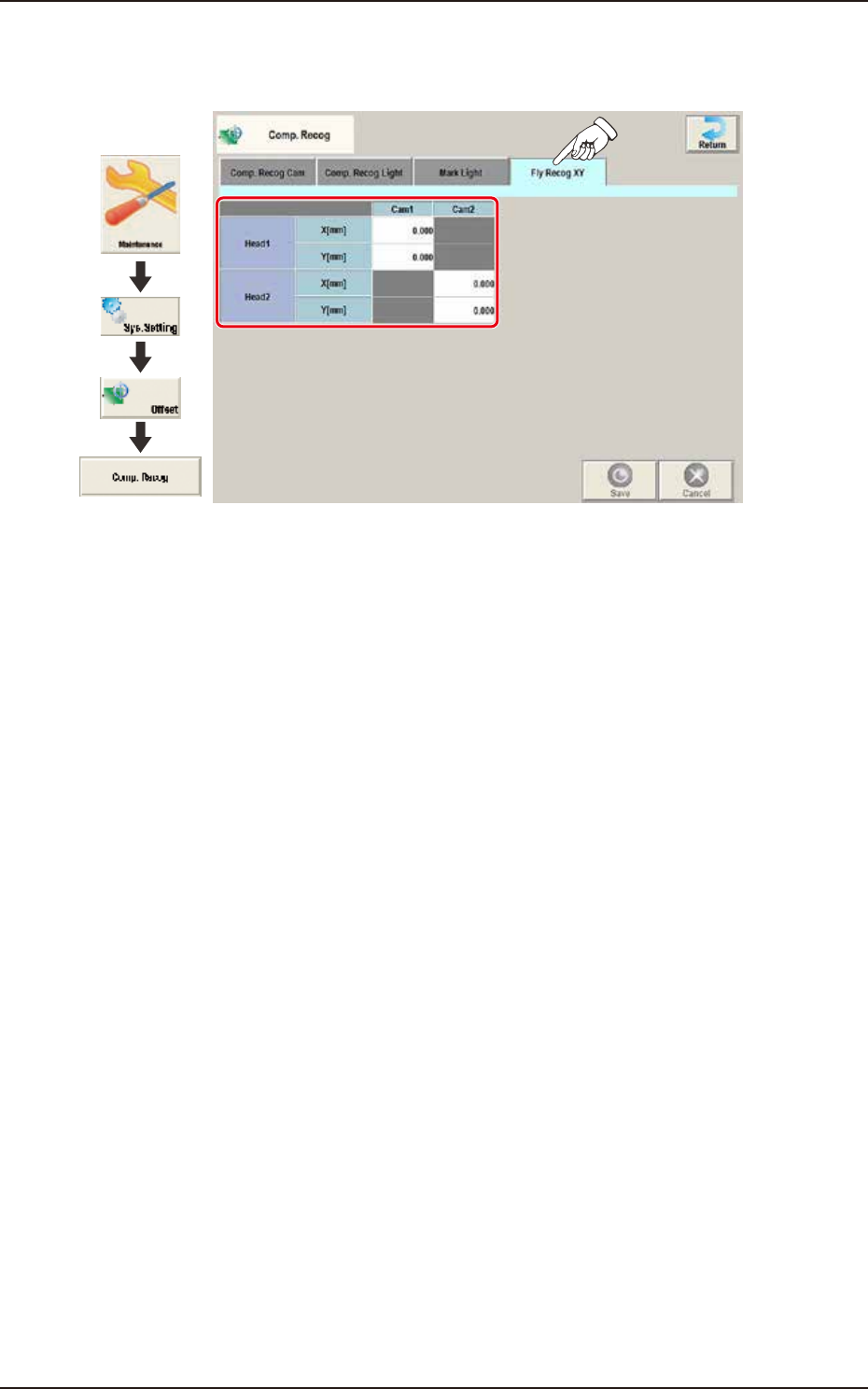
2.9.4 Fly Recog XY
Pressing the [Fly Recog XY] tab on the "Comp. Recog" window displays the following window.
Graphic
Development
F3B67
[1] Head 1 / Head 2
X [mm] / Y [mm]
Cam1 / Cam2
Obtain the deflections (caused mainly due to the delay time of the servo amplifier and the strobe)
of the images captured by the stopped component recognition camera (still image capture) and the
flying component recognition camera (fly image capture) and set the obtained values to adjust the
deviations in timing for image capture.
The set parameters are used to prevent a component from getting affected by the delay and staying
out of camera field of view.
EUKYX
2-53199-3100
2.10 Table
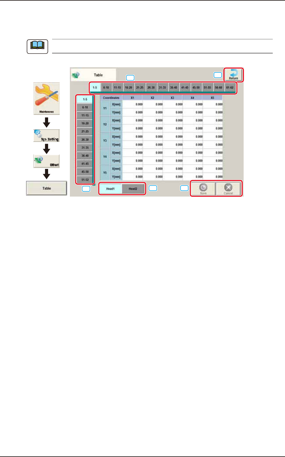
2.10 Table
Pressing the [Table] button on the "Offset Data" window displays the following window.
As for the "Head 2" tab sheets, the same contents as the "Head 1" tab sheet are displayed.
Graphic
Development
[1]
[2]
[3]
[4]
[5]
F3B68A
Enter the amount of deviation based on the specified distance when Head 1 has moved as far as the
specified distance (each grid point, X Direction: X1 through X40, Y Direction: Y1 through Y40) from
the PCB positioning reference.
These values are calculated automatically through the teaching operation and entered in each text
box.
[1] Head Select Tab
Using this tab, the head to be input is selected.
[2] Direction "X" Select Tab
Using this tab, the point on the grid in the direction "X" for the selected tab, is displayed.
[3] Direction "Y" Select Tab
Using this tab, the point on the grid in the direction "Y" for the selected tab, is displayed.
[4] [Return] button
Returns to the “Offset Data“ window.
[5] [Save] button
Saves the entered data.
[Cancel] button
Cancels the entered data and returns to the saved data.
Note