EUKYX-199-3100_G5S2_Instruction_Vol3_E.pdf - 第176页
EUKYX 2-28 199-3100 2.5 Head 2.5.6 Head Of fset Pressi ng the [Head O f fset] t ab on the "Head" window d ispl ays the fo l low ing w indo w . [1] [3] [2] [4] [5] [6] [7] Graphic Development F3B37A [ 1 ] He ad …
EUKYX
2-27199-3100
2.5 Head
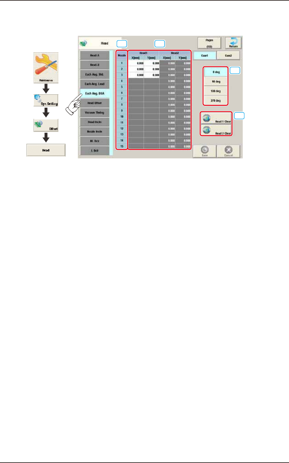
2.5.5 Each Ang. BGA
Pressing the [Each Ang. BGA] tab on the "Head" window displays the following window.
[1] [2]
[3]
[4]
Graphic
Development
F3B36A
[1] Nozzle 1 through 15
In this section, each nozzle No. is displayed.
[2] Head 1 and Head 2
X (Horizontal) and Y (Vertical) [mm]
When the applicable component is a BGA/CSP one, conversion and addition are made in response
to the placement angle while the target position for placement is being computed.
[3] Head Direction Selection Buttons
When this button is selected, the head direction is adjusted for each selected angle.
[4] [Head 1 Clear] Button, [Head 2 Clear] Button
Using these buttons, the data parameters for all the nozzles in the corresponding head are
performed.
EUKYX
2-28199-3100
2.5 Head
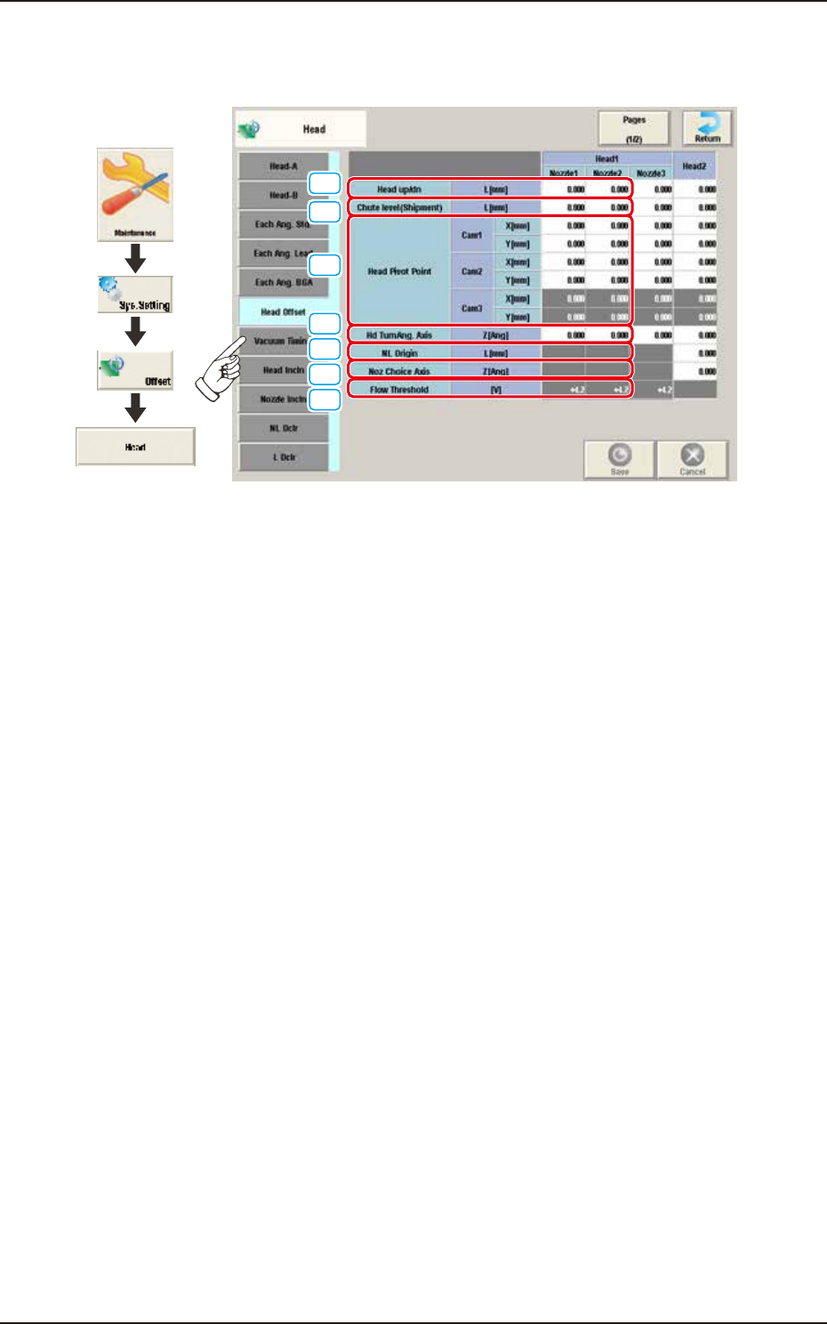
2.5.6 Head Offset
Pressing the [Head Offset] tab on the "Head" window displays the following window.
[1]
[3]
[2]
[4]
[5]
[6]
[7]
Graphic
Development
F3B37A
[1] Head up/dn
The set parameters are used to adjust the deviations (caused when the master nozzle is attached to
the head and lowered by the specified distance with the combined operations of the head and
nozzle U/D axes) based on the design value of the distance between the upper surface of PCB and
the lower surface of the nozzle. The amount of movement of each axis is separately reviewed.
When the measured value is greater than the design one, a plus sign must be affixed to the offset
data.
[2] Chute level (Shipment)
These offset parameters for backup are used to calculate the difference of the chute level value in
shipping from that in the head change, by means of measuring the chute level in advance when the
machine is shipped and performing the chute level height teaching when the head is changed.
EUKYX
2-29199-3100
2.5 Head
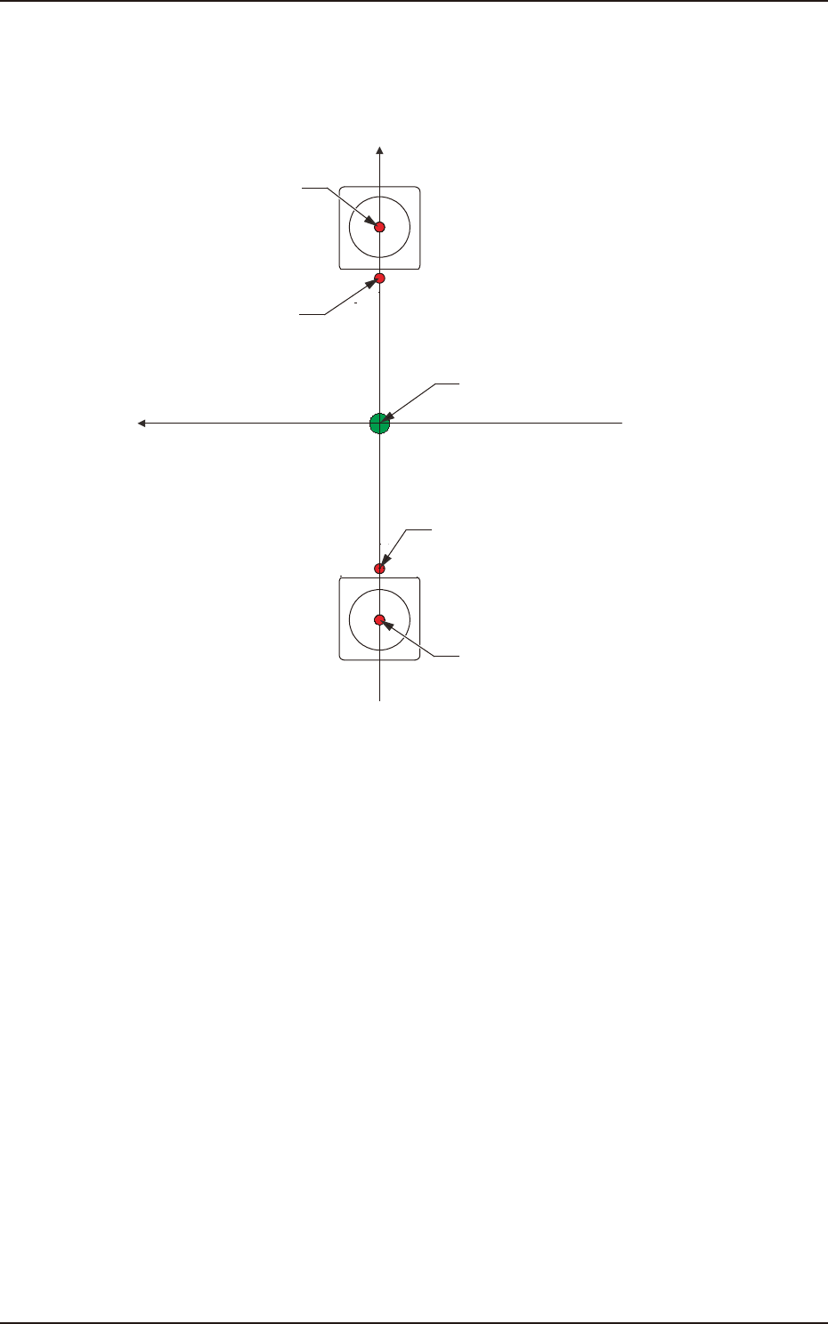
[3] Head Pivot Point
The set parameters are used to adjust the deviations in the design value between the head rotational
center and the center of the PEC recognition camera.
Xm-Ym :
Xm(+)
Ym(+)
Head Pivot Point
Center of PEC Recognition
Camera
Pm. Machine Reference
Coordinate Origin
Center of PEC Recognition Camera
Head Pivot Point
Machine Reference
Coordinate System
F3B38