EUKYX-199-3100_G5S2_Instruction_Vol3_E.pdf - 第172页
EUKYX 2-24 199-3100 2.5 Head 2.5. 2 Head- B Pressi ng the [Head- B] t ab on the "Head" window d isp la ys the fol low in g windo w . [1] [2] [3] [4] Graphic Development F3B32A [ 1 ] Nozzl e 1 through 1 5 In thi…
EUKYX
2-23199-3100
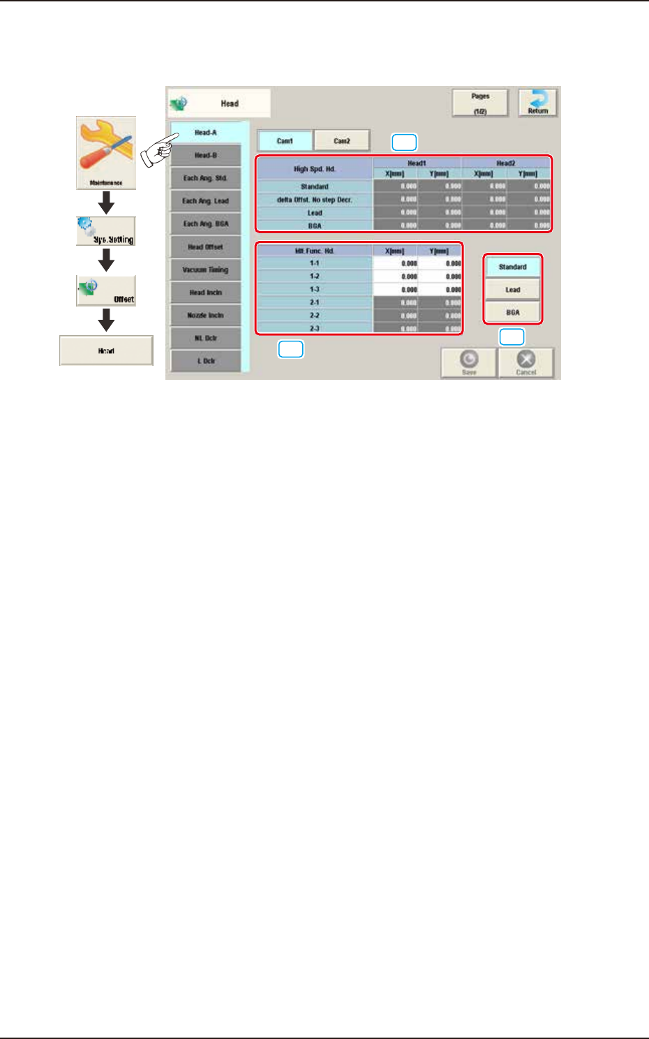
2.5 Head
2.5.1 Head-A
Pressing the [Head-A] tab on the "Head" window displays the following window.
[1]
[2]
[3]
Graphic
Development
F3B31A
[1] High Spd. Hd., Head 1 and Head 2 (X [mm], Y [mm] /Standard)
The set parameters are used to adjust the deviations of the head rotational centers caused
due to the movement of the head U/D axes.
delta Offst. No step Decr.
When no speed deceleration for component placement is specified in the library data and
the position for the placement is calculated, the proper deceleration rate is converted and
added.
Lead
When the library data set at the component placement is for the leaded components, the
value is converted or added in the placement target position calculation using this button.
BGA
When the library data set at the component placement is for the BGA components, the value
is converted and added in the placement target position calculation using this button.
[2] Mlt.Func. Hd. (X [mm], Y [mm])
The set parameters are used to adjust the deviations of the head rotational centers caused due to
the movement of the head U/D axes.
[3] [Standard] Button
When the applicable component is a standard one, the value is converted or added in the
placement target position calculation using this button.
[Lead] Button
When the applicable component is a leaded one, conversion and addition are made while
the target position for placement is being computed.
[BGA] Button
When the applicable component is a BGA/CSP one, conversion and addition are made while
the target position for placement is being computed.
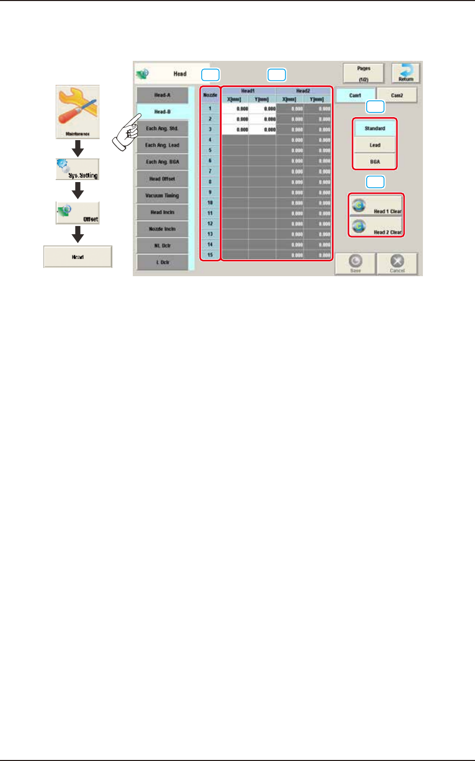
EUKYX
2-24199-3100
2.5 Head
2.5.2 Head-B
Pressing the [Head-B] tab on the "Head" window displays the following window.
[1] [2]
[3]
[4]
Graphic
Development
F3B32A
[1] Nozzle 1 through 15
In this section, each nozzle No. is displayed.
[2] Head 1 and Head 2
X (Horizontal) and Y (Vertical) [mm]
The set parameters are used to adjust the positional deviations of the nozzles caused due to the
movement of the nozzle U/D axes.
[3] [Standard] Button
When the applicable component is a standard one, conversion and addition are made while
the target position for placement is being computed.
[Lead] Button
When the applicable component is a leaded one, conversion and addition are made while
the target position for placement is being computed.
[BGA] Button
When the applicable component is a BGA/CSP one, conversion and addition are made while
the target position for placement is being computed.
[4] [Head 1 Clear] Button, [Head 2 Clear] Button
Using these buttons, the data parameters for all the nozzles in the corresponding head are
performed.
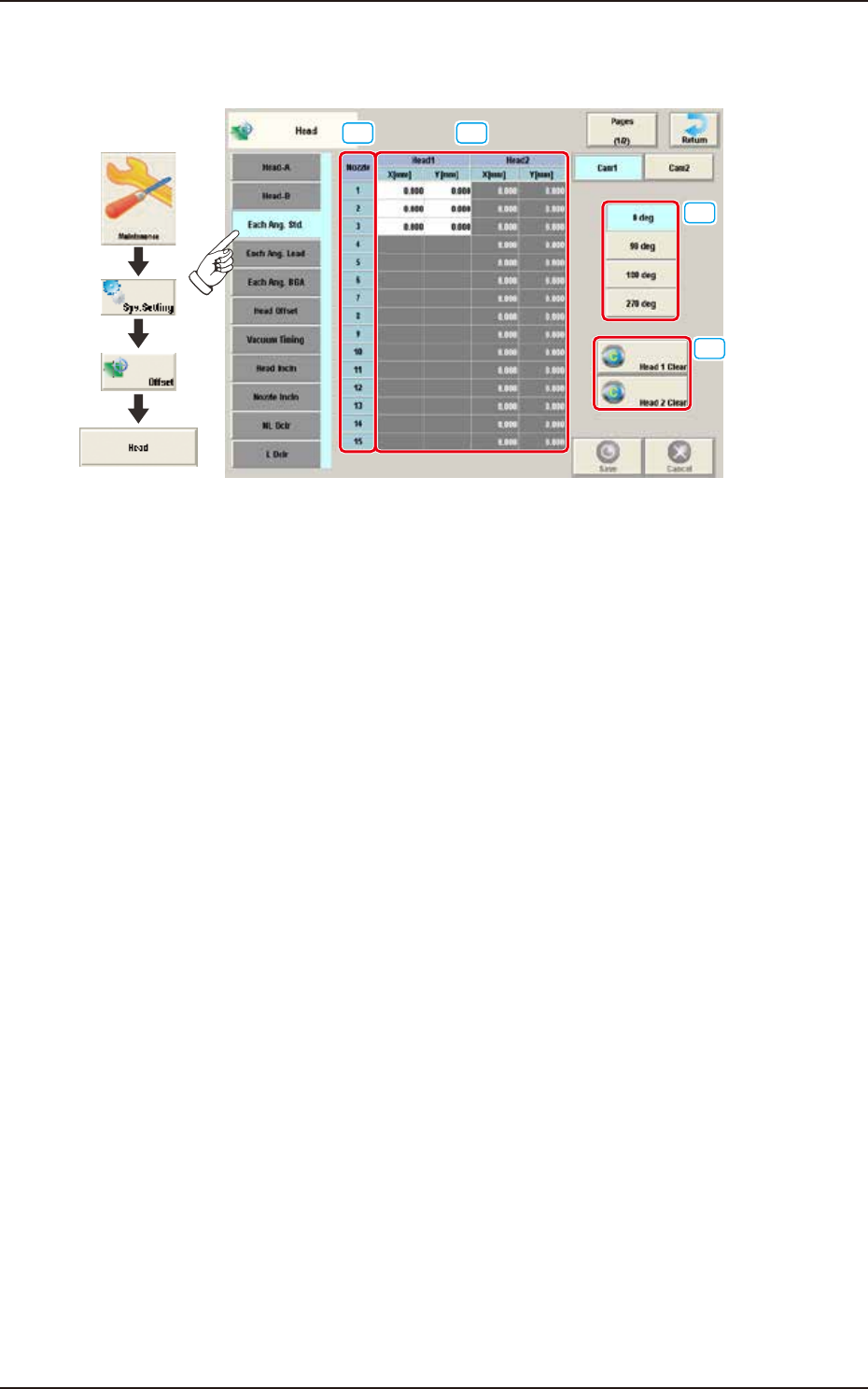
EUKYX
2-25199-3100
2.5 Head
2.5.3 Each Ang. Std
Pressing the [Each Ang. Std] tab on the "Head" window displays the following window.
[1] [2]
[3]
[4]
Graphic
Development
F3B34A
[1] Nozzle 1 through 15
In this section, each nozzle No. is displayed.
[2] Head 1 and Head 2
X (Horizontal) and Y (Vertical) [mm]
When the applicable component is a each angle one, conversion and addition are made in response
to the placement angle while the target position for placement is being computed.
[3] Head Direction Selection Buttons
When this button is selected, the head direction is adjusted for each selected angle.
[4] [Head 1 Clear] Button, [Head 2 Clear] Button
Using these buttons, the data parameters for all the nozzles in the corresponding head are
performed.