EUKYX-199-3100_G5S2_Instruction_Vol3_E.pdf - 第151页
EUKYX 2-3 199-3100 2.1 Device Offset 2. 1 Device Of fset Pressi ng the [Device Of fset ] but ton on the "Of fs et Data "d isp la ys the fol low in g w i n d o w. [1] [2] [3] [5] [4] Graphic Development F3B3 [ 1…
EUKYX
2-2199-3100
2. Offset Data
2. Offset Data
Pressing [Sys. Setting] - [Offset] buttons displays the following window.
Graphic
Development
F3B2
Do not change the parameters unless necessary. These parameters are factory-adjusted upon
shipment of the machine.
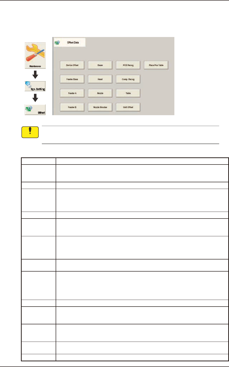
The Offset data is provided with the windows below and displayed by pressing relevant button.
Tab Description
Device Offset Adjusts the positional and angular deviations based on the design dimensions
representing the X/Y beam driving X/Y coordinates viewed from the PCB positioning
X/Y coordinates.
Feeder Base Adjusts the deviations based on the design values of each individual feeders.
FeederA This offset data is used independently for the machine. The corresponding tab sheet
enables the operator to adjust the positional deviations (viewed from the PCB
positioning X and Y coordinates) based on the design dimensions representing the
feeder pickup position and height for each individual feeder slot Nos. (Fdr Nos.).
FeederB Corrects the variations, etc., for each individual feeders.
Beam Corrects the positional and angular deviations based on the design dimension (the
distance between the placement reference coordinate origin and the center of the PEC
recognition camera at the head origin).
Head Corrects the positional deviation (placement coordinates) caused due to the deviation
of straightness (skew) of each individual head up/down axis guides and set up the
offset data for the distance between the scanning coordinate center of the PEC
camera and the head rotational center.
Nozzle Adjusts the deviations in height and rotational center of each nozzle and set the
measured values of the master nozzle (reference nozzle).
Nozzle Stocker Sets the offset data for adjustment of positional deviations compared with the design
dimensions of the nozzle stocker unit position (viewed from the PCB positioning
reference) and the offset data for adjustment of positional deviations compared with
the design dimensions (viewed from the PCB positioning reference) for each individual
addresses 1 through 15 of 1-1 to 2-2.
PCB Recog Adjusts the horizontal swing (tilt) of the PEC recognition camera.
Comp. Recog Sets the offset data that will be used to adjust the positional deviation based on the
design dimension (the distance between the machine reference coordinate origin and
the center of the component recognition camera).
Table Sets the amount of deviation based on the specified distance when each head (Heads
1 through 2) has moved as far as the specified distance (each grid point) from the
PCB positioning reference.
Unit Offset Used when the multi-layer tray feeder is used.
Note: Refer to "GS-FP600 Multi-Layer Tray Feeder" for details.
Place Pos Table
This offset data corrects the feed inaccuracy of the X/Y axis of the placement position.
Notice
EUKYX
2-3199-3100
2.1 Device Offset
2.1 Device Offset
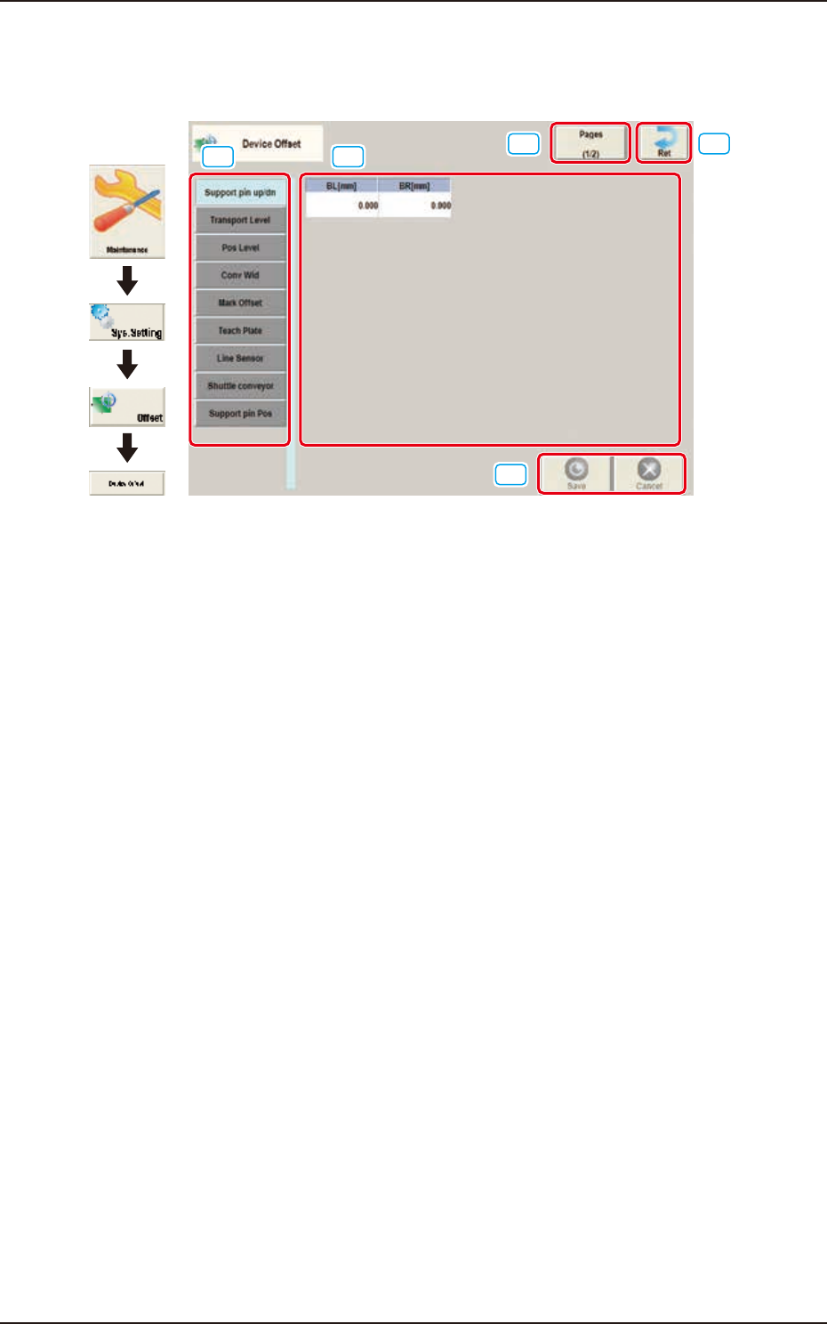
Pressing the [Device Offset] button on the "Offset Data"displays the following window.
[1] [2]
[3]
[5]
[4]
Graphic
Development
F3B3
[1] Offset Select Tab
When this button is pressed, the offset data for the selected tab is displayed.
[2] Offset Data Display Section
In this section, the offset data selected in step [1] is displayed.
[3] Page Change Button
Using this button, the offset editing page is changed.
[4] [Ret] button
When this button is pressed, the window returns to the "Offset Data" window.
[5] [Save] button
When this button is pressed, the input data is saved.
[Cancel] button
When this button is pressed, the input data is cancelled and window returns to the save data.
EUKYX
2-4199-3100
2.1 Device Offset
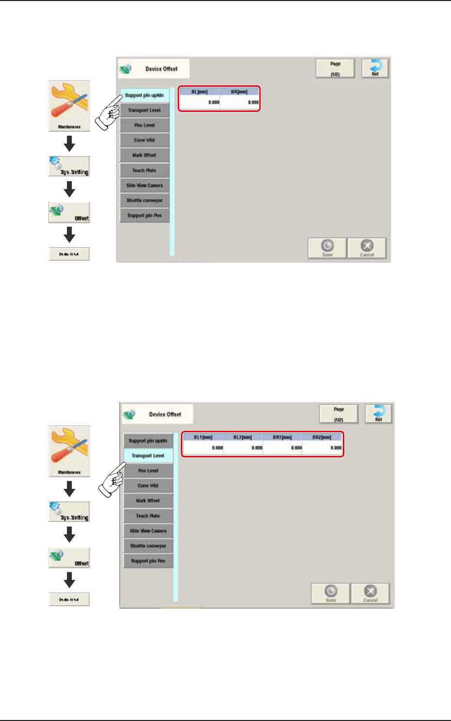
2.1.1 Support pin up/dn
Pressing the [Support pin up/dn] tab on the "Device Offset" window displays the following window.
Graphic
Development
F3B4A-1
BL [mm] / BR [mm]
This is the offset data for the origin position of the support pin up/down axis which ascends or
descends during PCB positioning.
A plus (+) value decreases the ascending stroke during PCB positioning.
2.1.2 Transport Level
Pressing the [Transport Level] tab on the “Device Offset” window displays the following window.
Graphic
Development
F3B5A
BL1 [mm] / BL2 [mm] / BR1 [mm] / BR2 [mm]
Each parameters are used to correct the positional deviations in PCB transfer positioning in
comparison with Support pin up/down operation.